 Michael Gardi
The first thing that I noticed when I started the wiring was that the switch assembly wires (purple) and the light panel LEDs (grey hexes) were overlapping, making my life harder than it had to be.
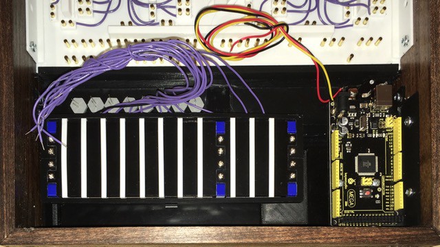
So I removed the switch assembly and rebuilt it, moving the eight brown rocker switch wires to the bottom of the assembly (the pulse switches were OK). There is a nice channel on that side to run the wires between the frame and the assembly itself. Following this wiring diagram (which has a small change to the potentiometer power wire from the one posted previously)...

...it was pretty clear sailing and here is the result:
For reference the wire colors are:
- purple - switch inputs to Arduino
- grey - switch outputs from Arduino
- white - clock out and clock delay control from and to Arduino
- yellow - potentiometer input to Arduino
- red - power +, 9V to Arduino, 5V from Arduino
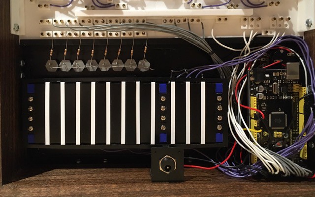
- black - ground
The LEDs are wired directly to the lamp inputs with a 4K limiting resistor (large enough to keep the brightness down to incandescent levels). While wiring the LEDs I noticed a pretty big goof on my part. The label for the lamp terminals should have read LAMP INPUTS. Doh!

Oh well nothing to do about it now. I have updated the patch panel STL file but will live with my error on this build.
All that's left to do now is run power up to the PCBs and the HIGH and GND terminals. Very excited to be this close.
Discussions
Become a Hackaday.io Member
Create an account to leave a comment. Already have an account? Log In.