 Torbjörn Lindholm
This project is entirely based on http://danyk.cz/avr_aku_en.html with help from the author.
Read the assembly notes before you try it!
There are two versions -- one with all through-hole parts (recommended) and one experimental version with surface-mount parts peppered in. Both should work identically, but I cannot guarantee it.
The board is designed to fit into the 10x10cm limit most PCB manufacturers have. If you can afford it, get it made with thicker copper layer, however 1oz is fine too. The tracks are made to handle it.
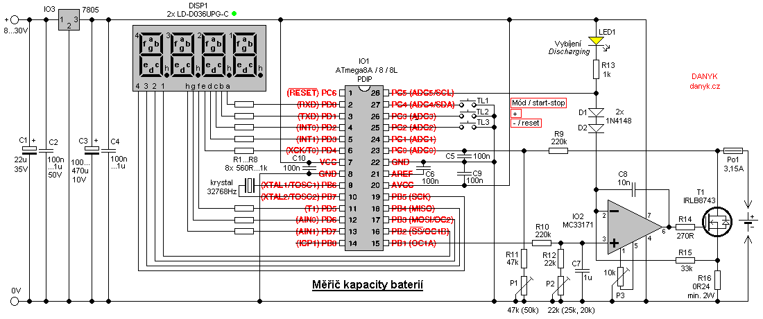
The schematic below is his original schematic. If there are any issues, please let me know.
Assembly notes:
On SMD boards, install all SMD parts first before you solder any THT parts, from small to big. Else, you may encounter issues with clearance.
You may substitute few parts as long as they are compatible -- Google is your friend on this. You might have noticed I've replaced few parts from the schematic already. MC33171 is compatible with TL081, but I wasn't able to get an exact replacement for IRLB8743 since all of them didn't exist on KiCad's library. As long as it has a gate voltage of 5V and it can withstand a current close or equal to the original part, I think it should be fine.
On SMD version, you need to solder the tab of 7805 voltage regulator to the pad on the board to provide a ground connection. It doesn't draw much power so the connection, so as long as it's solid, doesn't matter.
The reason the power resistor being huge is for accommodating various types of resistors, including homemade hand-wound resistor. It's spread to two resistors to split the load, but if you want, you can use one 0.24 ohm power resistor with rating of 2W or higher. You cannot use regular quarter-watt resistor for this. You NEED a high-power resistor.
The fuse is an automotive fuse. I wanted to use the fuse holder, but KiCad again didn't have a part ready for it, thus I had to make a compromise. This should be addressed in the future revisions.
I did make the board easier to assemble even with cheap tools, so I hope it paid off.
Warning:
DO NOT SCREW VOLTAGE REGULATOR AND MOSFET TO THE SAME HEATSINK. Doing this will cause a dead short to ground and fry your board! I designed the layout to dissuade users from doing that (the voltage regulator is rotated and there is an arrow on the board)
The heatsinking pad on the SMD board near the MOSFET is NOT a ground pad! DO NOT connect those two together!
You must put an additional heatsink block on top of the MOSFET on the SMD version board, or install a fan to blow on the component. Failing to do so may cause overheating, which may result in a failure and increase the fire risk.
Calibration procedure:
(From Danyk's page, edited for clarity and to reflect the actual board layout)
First of all, this is how the meter and the board is connected:
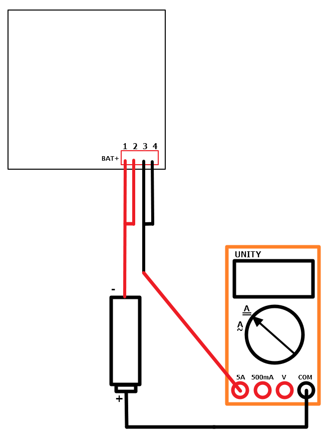
- Get a current meter capable of measuring up to 5A of current. (Sadly, the free/cheap DMMs may not work safely for this, so prepare to borrow it off someone)
Set RV2 to center position.
Connect a battery capable of at least 2.56 A discharge current and a current meter in series with it (or use an adjustable power supply capable of outputting such current).
- Measure the voltage of the battery.
- Adjust RV3 until the voltage display matches the actual voltage of the battery.
Set the desired discharge current to 2.56 A.
Start the discharge (press and hold the MODE button - leftmost button)
Set RV1 so that the actual discharge current equals to the chosen value (2.56A).
Set the discharge current to 0.01 A.
Adjust the offset of inputs of the OP-AMP using RV2 - set RV2 so that the actual current is 0.01A.
- You're now ready to go! Put a bit of tape or hot glue over the potentiometer to prevent it from getting moved.
Control:
(From Danyk's page)
The battery meter is controlled with 3 buttons: "Mode", "UP" and "DOWN".
Mode button switches six display states:
- Display the actual voltage (0.00 V - 20.4 V).
- Measured...
 Manuel Tosone
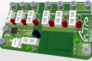
 McGill Formula Electric
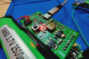
 Matthew James Bellafaire
 The Big One
hi what's need to change in software to test 5s lit-ion battery ? for hardware i thing with p1 calibrating there's no problem