0%
0%
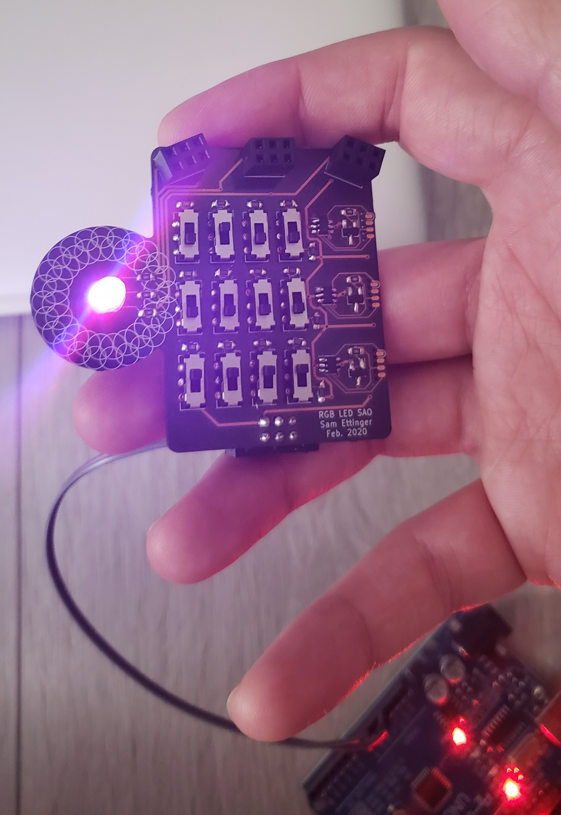
12 switches, 1 LED, 1 SAO
No knobs! No 555s! No reason whatsoever!
 Sam Ettinger
Become a Hackaday.io member
Already have an account? Log in.
Just one more thing
To make the experience fit your profile, pick a username and tell us what interests you.
Pick an awesome username
hackaday.io/
Your profile's URL: hackaday.io/username. Max 25 alphanumeric characters.
Pick a few interests
Projects that share your interests
People that share your interests


 Jan
Jan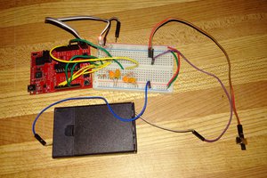
 Petri Varsa
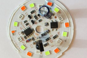
 Tim
Tim
 Alex
Alex
Really? Microcontroller? Three of them!? for this task?
It would be so much easier to give each switch its (roughly) binary weighted resistor, let's use 220, 470, 1k and 2k2 and these combined resistors control the current to the LED, switched off or in parallel.