kmatch98
Background
This is a 3D LED matrix cylinder inspired by makeTVee and adapted for 3D printing. The concept is that the matrix grid is printed flat and rolled up into a cylinder. The LED's are installed and then the sky is the limit on what you can do!
The Inspiration - makeTVee
This cylindrical LED matrix from makeTVee is where it all started. He uses laser cut card board for the sections.
https://hackaday.io/project/162035-led-matrix-cylinder
I don't have access to a laser cutter but wanted a matrix, so I adapted his design to use 3D printing for the mechanical and ESP32-based WiFi connected Feather board (Adafruit Huzzah32) as the controller.
Bill of Materials
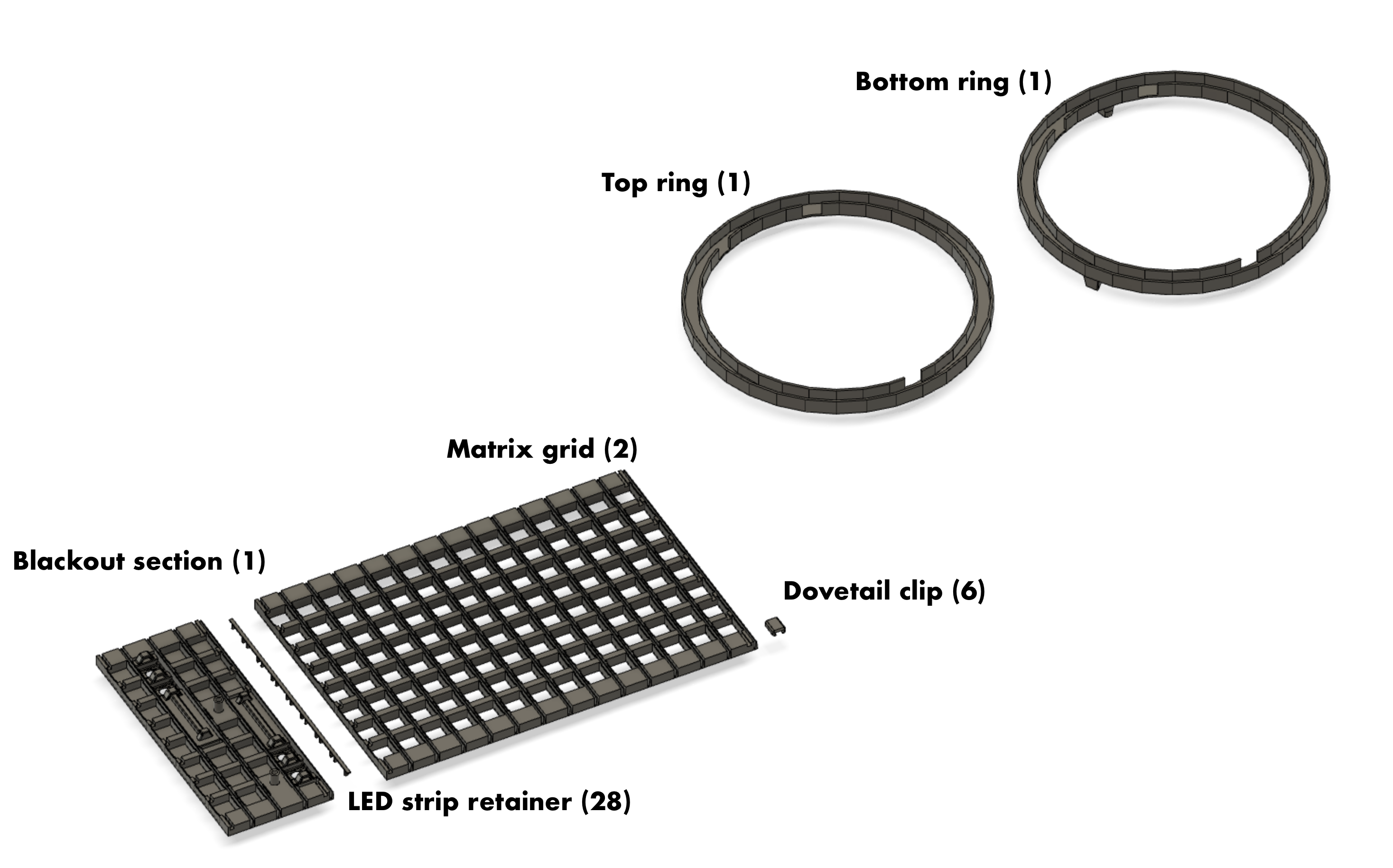
3D printed pieces
- Matrix grid (2 large pieces)
- Blackout section with four button holes and mounting location for breadboard
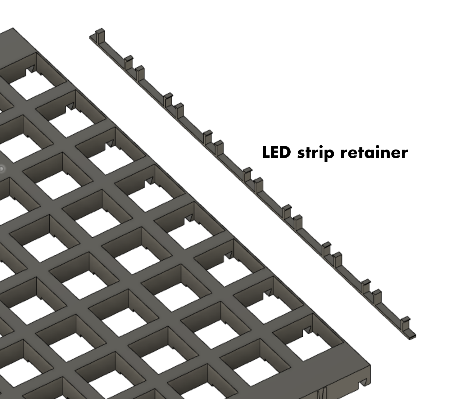
- LED strip retainers (28 quantity, probably overkill)
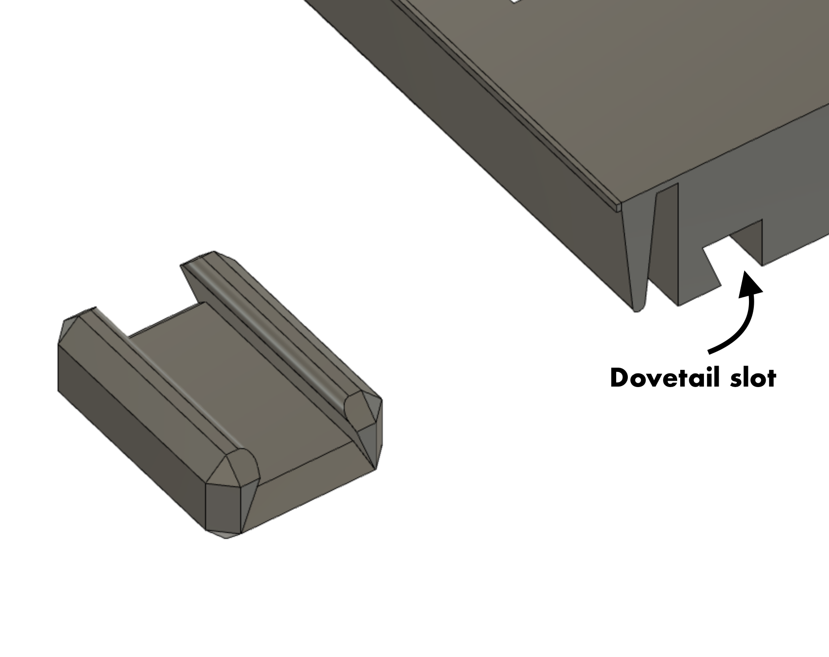
- Dovetail clip - Connect the sections together in dovetail slots (6 quantity)
- Top ring (no feet)
- Bottom ring (with feet, or use no feet if using a wooden frame)
- (optional) Wood circle for top and bottom and a way to hold them on.
Electronics components
- WS2812 LED strip, 60 LEDs per meter, 5 meters, cut into 28 LED strips (8 quantity)
- Hookup wire
- Tactile buttons, 12mm (4 quantity)
- Adafruit Feather Huzzah32 (ESP32) - Soldered directly to protoboard or onto removable headers
- Level shifter - part number 74AHCT125 (may be optional but I used it anyway)
- 470 Ohm resistor - for connection to LED data line
- Half sized protoboard
- Miscellaneous wire, solder and flux
- 100 uF, 25V electrolytic capacitors - Across 5V USB bus and across the 3.3V (2 quantity)
- USB cable
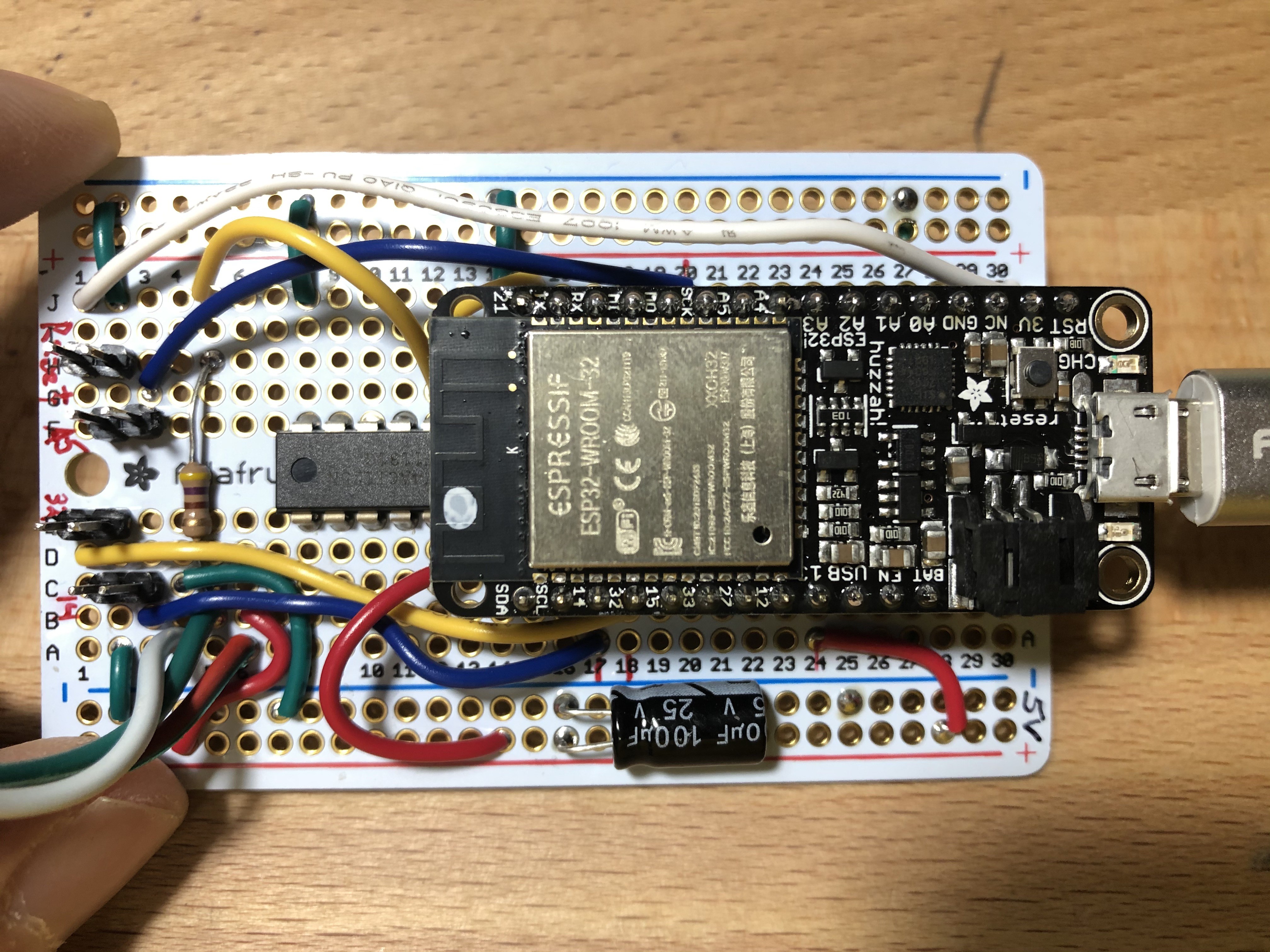
Electrical connections to the Feather Huzzah32 (ESP32)
- LED signal - Pin 21 - connects to LED strip data input through the Level Shifter
- Button A - Pin 14
- Button B - Pin 32
- Button C - Pin A5
- Reset - RESET
Mechanical Design - Final
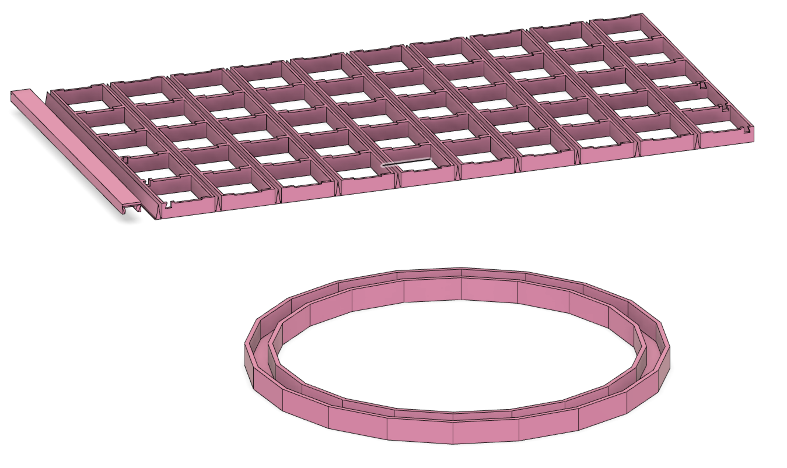
The LED matrix holder is designed to print flat on the 3D printer and then roll up into the cylindrical shape.
The largest panel is designed to fit onto a 12x12 inch bed (Creality CR-10S in my case). The large panel accommodates an 8x14 array of LEDs (using 60 LEDs/m strips). Two of the matrix sections are required to make the 8x28 LED array. The LED strips fit into recesses in the matrix. The LED strips run horizontal with 28 LEDs in each strip. In contrast to makeTVee, I ran my strips horizontally to reduce the number of connections as well as to simplify hiding the wiring.
A "blackout" section (8x4 worth of LED) is provided for holding the buttoms and the protoboard. So, connecting these three sections provides an effective 32 sided polygon worth of sections.
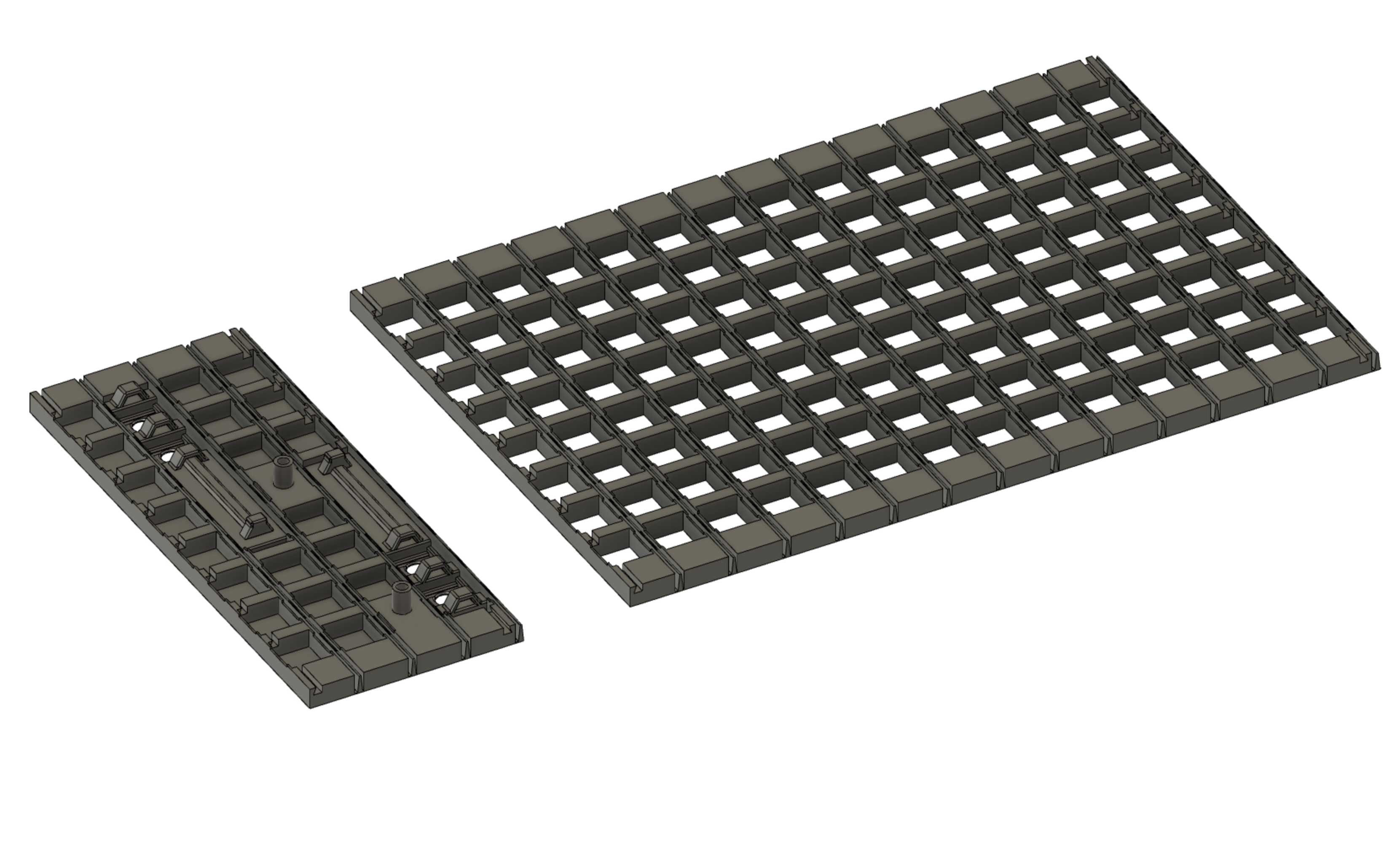
The LED matrix is completed using the LED strip retainers and the dovetail clips.

The sections are butted together and joined using the dovetail clips in the dovetail slots.
After installing the LEDs into the slots in the matrix, each of the 28 sections receives an LED strip retainer to keep the LED strip in place in its respective slot. These retainers slighly flex to maintain friction on the matrix edges.
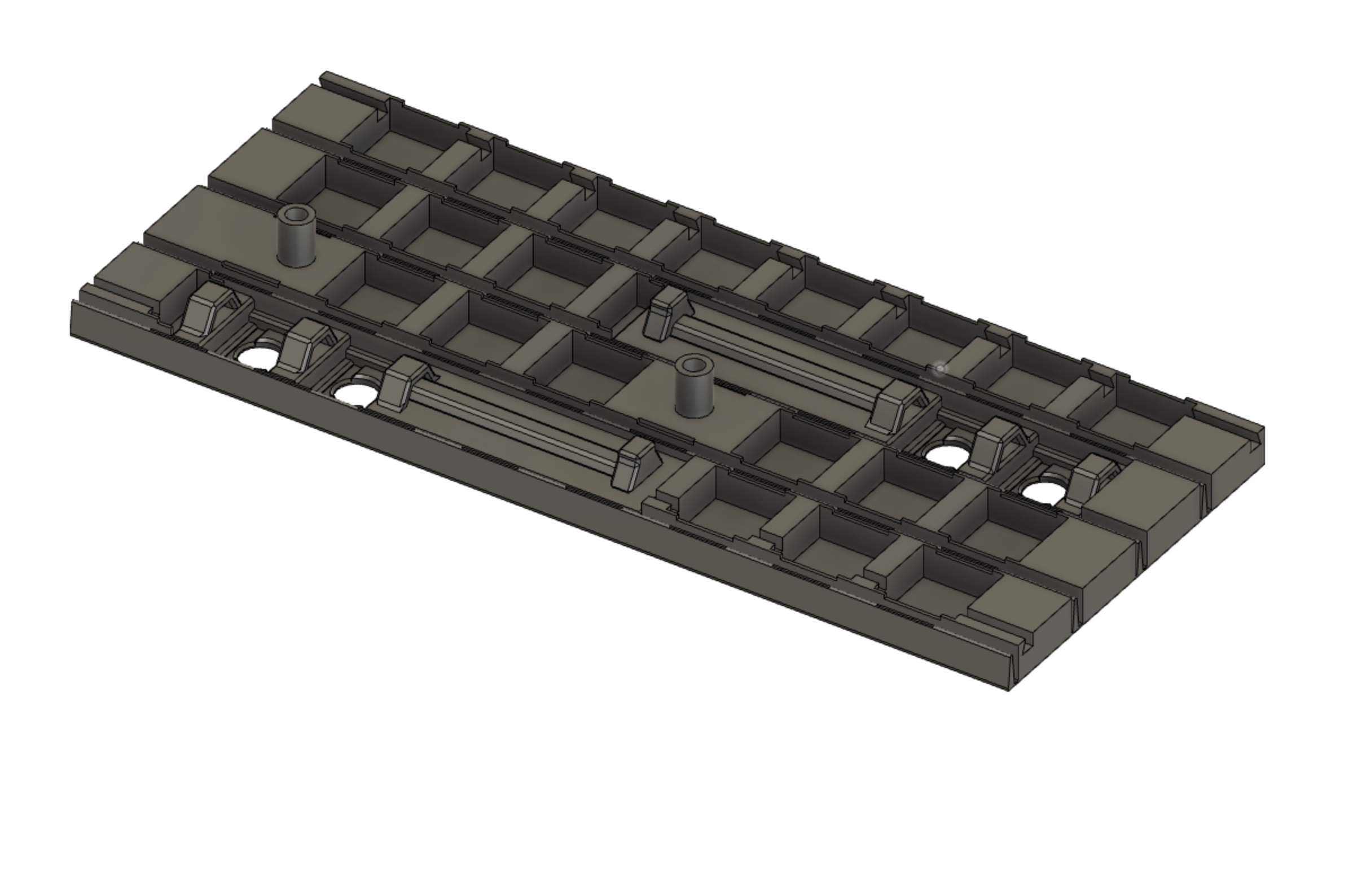
The blackout section provides room for 4 buttons and M3 bolt through holes for mounting the prototype board.
The top ring and bottom ring (with feet) have cutouts to receive the dovetail clips between the matrix sections.
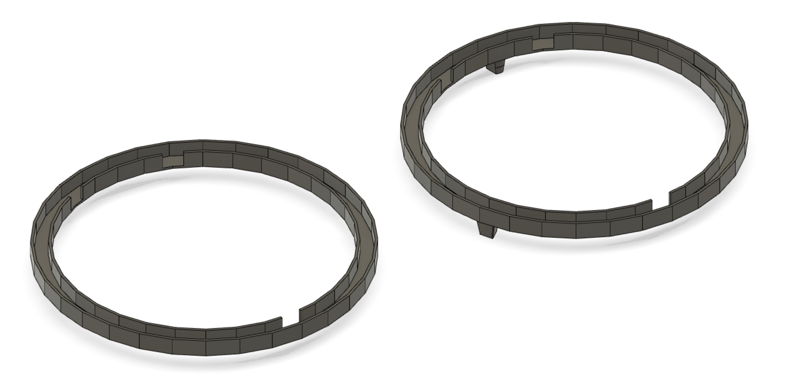
Note: The USB cable snakes under the bottom ring feet and into the Feather's USB port. There's probably a cleaner way of doing this to have the USB port accessible from the blackout panel, but I didn't bother with it.
Test Program (Arduino)
Here is a test program that shows a rainbow and then goes through red, green, blue to check out all the LEDs. Also you can check the button operation using the serial console.
This test program was based on Adafruit's NeoPixel matrix code but modified to run on the ESP32 by using the NeoPixelBrightnessBus library by Makuna.
// Which pin on the Arduino is connected to the NeoPixels?
// On a Trinket or Gemma we suggest changing this to 1:
#define LED_PIN    21

// How many NeoPixels are attached to the Arduino?
#define LED_COUNT 28*8


// A basic everyday NeoPixel strip test program.

// NEOPIXEL BEST PRACTICES for most reliable operation:
// - Add 1000 uF CAPACITOR between NeoPixel strip's + and - connections.
// NeoPixelTest
// This example will cycle between showing four pixels as Red, Green, Blue, White
// and then showing those pixels as Black.
//
// Included but commented out are examples of configuring a NeoPixelBus for
// different color order including an extra white channel, different data speeds, and
// for Esp8266 different methods to send the data.
// NOTE: You will need to make sure to pick the one for your platform
//
//
// There is serial output of the current state so you can confirm and follow along
//

#include <NeoPixelBrightnessBus.h>


// const uint16_t PixelCount = 28*8; // this example assumes 4 pixels, making it smaller will cause a failure
// const uint8_t PixelPin = 21;  // make sure to Set this to the correct pin, ignored for Esp8266

#define colorSaturation 128

// three element pixels, in different order and speeds
NeoPixelBrightnessBus<NeoGrbFeature, Neo800KbpsMethod> strip(LED_COUNT, LED_PIN);// - MINIMIZE WIRING LENGTH between microcontroller board and first pixel.


// - NeoPixel strip's DATA-IN should pass through a 300-500 OHM RESISTOR.
// - AVOID connecting NeoPixels on a LIVE CIRCUIT. If you must, ALWAYS
//   connect GROUND (-) first, then +, then data.
// - When using a 3.3V microcontroller with a 5V-powered NeoPixel strip,
//   a LOGIC-LEVEL CONVERTER on the data line is STRONGLY RECOMMENDED.
// (Skipping these may work OK on your workbench but can fail in the field)

//#include <Adafruit_NeoPixel.h>

#define BUTTONA 14
#define BUTTONB 32
#define BUTTONC 5


RgbColor red(colorSaturation, 0, 0);
RgbColor green(0, colorSaturation, 0);
RgbColor blue(0, 0, colorSaturation);
RgbColor white(colorSaturation);
RgbColor black(0);

HslColor hslRed(red);
HslColor hslGreen(green);
HslColor hslBlue(blue);
HslColor hslWhite(white);
HslColor hslBlack(black);


// Declare our NeoPixel strip object:
//Adafruit_NeoPixel strip(LED_COUNT, LED_PIN, NEO_GRB + NEO_KHZ800);
// Argument 1 = Number of pixels in NeoPixel strip
// Argument 2 = Arduino pin number (most are valid)
// Argument 3 = Pixel type flags, add together as needed:
//   NEO_KHZ800  800 KHz bitstream (most NeoPixel products w/WS2812 LEDs)
//   NEO_KHZ400  400 KHz (classic 'v1' (not v2) FLORA pixels, WS2811 drivers)
//   NEO_GRB     Pixels are wired for GRB bitstream (most NeoPixel products)
//   NEO_RGB     Pixels are wired for RGB bitstream (v1 FLORA pixels, not v2)
//   NEO_RGBW    Pixels are wired for RGBW bitstream (NeoPixel RGBW products)


// Setup() function -- runs once at startup --------------------------------

void setup() {
  // These lines are specifically to support the Adafruit Trinket 5V 16 MHz.
  // Any other board, you can remove this part (but no harm leaving it):
#if defined(__AVR_ATtiny85__) && (F_CPU == 16000000)
  clock_prescale_set(clock_div_1);
#endif
  // END of Trinket-specific code.

  pinMode(BUTTONA, INPUT_PULLUP);
  pinMode(BUTTONB, INPUT_PULLUP);
  pinMode(BUTTONC, INPUT_PULLUP);

  Serial.begin(115200);
  delay(3000);
  Serial.println("Ready to go");

  attachInterrupt(digitalPinToInterrupt(BUTTONA), buttonAhandler, FALLING);
  attachInterrupt(digitalPinToInterrupt(BUTTONB), buttonBhandler, FALLING);
  attachInterrupt(digitalPinToInterrupt(BUTTONC), buttonChandler, FALLING);
  interrupts();

  strip.Begin();           // INITIALIZE NeoPixel strip object (REQUIRED)
  strip.Show();            // Turn OFF all pixels ASAP
  strip.SetBrightness(32); // Set BRIGHTNESS to about 1/5 (max = 255)
}


void buttonAhandler() {
  Serial.println("A pressed");
}

void buttonBhandler() {
  Serial.println("B pressed");
}

void buttonChandler() {
  Serial.println("C pressed");
}

// loop() function -- runs repeatedly as long as board is on ---------------

void loop() {


  // Do a theater marquee effect in various colors...
  //  theaterChase(strip.Color(127, 127, 127), 50); // White, half brightness
  //  theaterChase(strip.Color(127,   0,   0), 50); // Red, half brightness
  //  theaterChase(strip.Color(  0,   0, 127), 50); // Blue, half brightness

  rainbow(10);             // Flowing rainbow cycle along the whole strip
  //theaterChaseRainbow(50); // Rainbow-enhanced theaterChase variant

  // Fill along the length of the strip in various colors...
  colorWipe(red, 50); // Red
  colorWipe(green, 50); // Green
  colorWipe(blue, 50); // Blue
  colorWipe(white, 50); // white
}


RgbColor WheelColor(uint16_t wheelValue) {
  // divide the wheelValue by 360.0f to get a value between 0.0 and 1.0 needed for HslColor
  return HslColor(wheelValue / 360.0f, 1.0f, 0.5f); // this will autoconvert back to RgbColor
}

// Some functions of our own for creating animated effects -----------------

// Fill strip pixels one after another with a color. Strip is NOT cleared
// first; anything there will be covered pixel by pixel. Pass in color
// (as a single 'packed' 32-bit value, which you can get by calling
// strip.Color(red, green, blue) as shown in the loop() function above),
// and a delay time (in milliseconds) between pixels.
void colorWipe(RgbColor color, int wait) {
  for (int i = 0; i < strip.PixelCount(); i++) { // For each pixel in strip...
    strip.SetPixelColor(i, color);         //  Set pixel's color (in RAM)
    strip.Show();                          //  Update strip to match
    delay(wait);                           //  Pause for a moment
  }
}

// Theater-marquee-style chasing lights. Pass in a color (32-bit value,
// a la strip.Color(r,g,b) as mentioned above), and a delay time (in ms)
// between frames.
void theaterChase(RgbColor color, int wait) {
  for (int a = 0; a < 10; a++) { // Repeat 10 times...
    for (int b = 0; b < 3; b++) { //  'b' counts from 0 to 2...
      strip.ClearTo(black);         //   Set all pixels in RAM to 0 (off)
      // 'c' counts up from 'b' to end of strip in steps of 3...
      for (int c = b; c < strip.PixelCount(); c += 3) {
        strip.SetPixelColor(c, color); // Set pixel 'c' to value 'color'
      }
      strip.Show(); // Update strip with new contents
      delay(wait);  // Pause for a moment
    }
  }
}

// Rainbow cycle along whole strip. Pass delay time (in ms) between frames.
void rainbow(int wait) {
  // Hue of first pixel runs 5 complete loops through the color wheel.
  // Color wheel has a range of 65536 but it's OK if we roll over, so
  // just count from 0 to 5*65536. Adding 256 to firstPixelHue each time
  // means we'll make 5*65536/256 = 1280 passes through this outer loop:
  for (uint16_t firstPixelHue = 0; firstPixelHue < 5 * 360; firstPixelHue += 1) {
    for (int i = 0; i < strip.PixelCount(); i++) { // For each pixel in strip...
      // OffSet pixel hue by an amount to make one full revolution of the
      // color wheel (range of 65536) along the length of the strip
      // (strip.PixelCount() steps):
      int pixelHue = (firstPixelHue + (i * 360 / strip.PixelCount())) % 360;
      // strip.ColorHSV() can take 1 or 3 arguments: a hue (0 to 65535) or
      // optionally add saturation and value (brightness) (each 0 to 255).
      // Here we're using just the single-argument hue variant. The result
      // is passed through strip.gamma32() to provide 'truer' colors
      // before assigning to each pixel:
      strip.SetPixelColor(i, WheelColor(pixelHue));
    }
    strip.Show(); // Update strip with new contents
    delay(wait);  // Pause for a moment
  }
}

// Rainbow-enhanced theater marquee. Pass delay time (in ms) between frames.
void theaterChaseRainbow(int wait) {
  int firstPixelHue = 0;     // First pixel starts at red (hue 0)
  for (int a = 0; a < 30; a++) { // Repeat 30 times...
    for (int b = 0; b < 3; b++) { //  'b' counts from 0 to 2...
      strip.ClearTo(black);         //   Set all pixels in RAM to 0 (off)
      // 'c' counts up from 'b' to end of strip in increments of 3...
      for (int c = b; c < strip.PixelCount(); c += 3) {
        // hue of pixel 'c' is offSet by an amount to make one full
        // revolution of the color wheel (range 65536) along the length
        // of the strip (strip.PixelCount() steps):
        int      hue   = firstPixelHue + c * 65536L / strip.PixelCount();
        //       uint32_t color = strip.gamma32(strip.ColorHSV(hue)); // hue -> RGB

        uint32_t color = hue; //**** fix this to the NeoGamma style for NeoPixelBus

        strip.SetPixelColor(c, color); // Set pixel 'c' to value 'color'
      }
      strip.Show();                // Update strip with new contents
      delay(wait);                 // Pause for a moment
      firstPixelHue += 65536 / 90; // One cycle of color wheel over 90 frames
    }
  }
}
Mechanical Design - Preliminary
Here is a first cut at the flat 3D design and a trial print.
This was printed flat on the bed, then rolled up and connected at each end with a dovetail-like bracket. The connector can be improved upon.
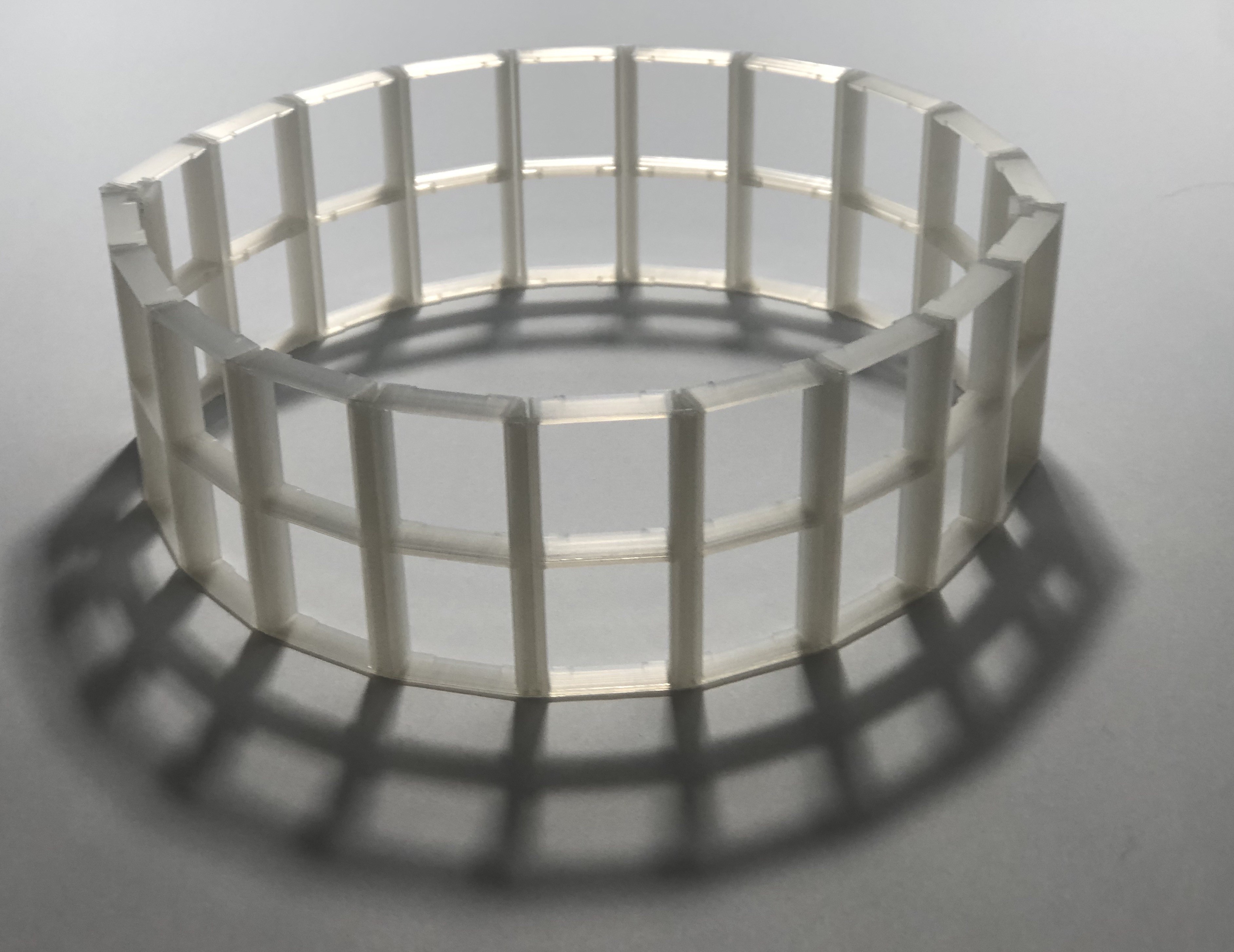
I plan to add a ring at the top and bottom to house the electronics and the wiring. I'm considering the best orientation of the LED strips. Vertical orientation (as used by makeTVee) will prevent the strips from being flexed. Vertical orientation requires wiring for each column (20 columns for makeTVee's design). However, horizontal orientation will reduce the amount of end wiring (to just the number of rows, 5 rows for the design of makeTVee).
Wiring
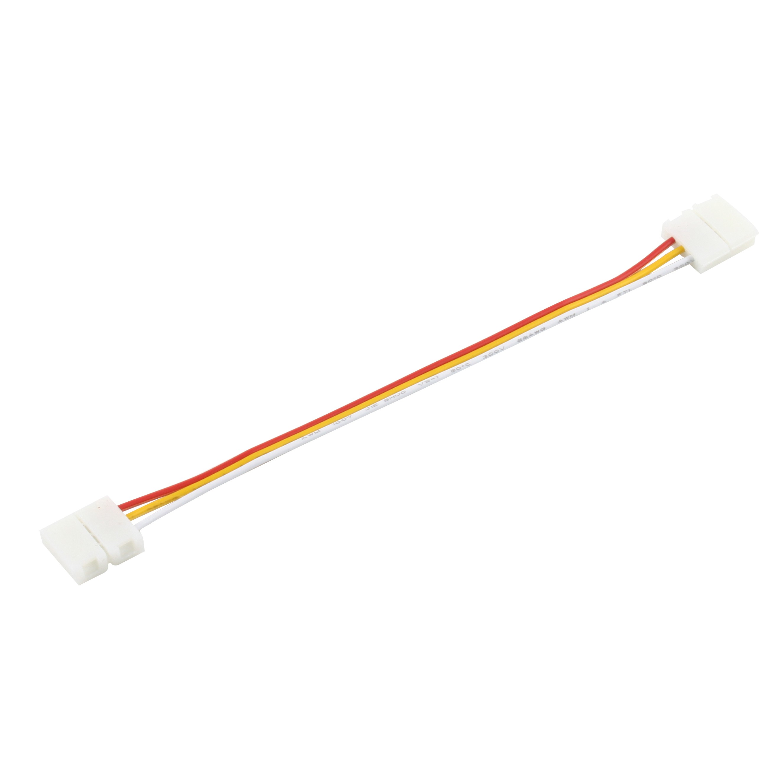
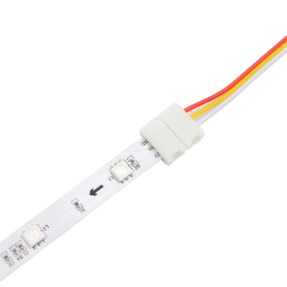
I ordered some solderless LED strip connectors. I'm eager to see if they are sufficiently reliable to work on this project. These connectors were delayed so I just soldered the strips together.