 Mateo Estigarribia
For those who wonder why use a PIC16F887 and not some development interface such as arduino or perhaps raspberry, I can say that it is because in the school they made it a goal to use this microcontroller in order to increase our knowledge and perhaps as an entry to what would be typical of teaching such as arduino, raspberry or plc.
It costs me a lot to make a systematic explanation of how the project works, the truth is that we went in phases and perhaps therein lies the secret. The idea was to get the mechanical track system working first, then the radio communication system, and finally the robotic arm. The video camera is nothing more than a WiFi camera, we could not establish a connection to the xbee due to lack of time, we were against the clock and we no longer had time to investigate further, yes, I suppose it would have been some serial communication with TX / RX ports; In the same way, I have to say something very important, and that is that we deal with it in an extremely simple way to understand in every way, from programming, the use of components and mechanical structure.
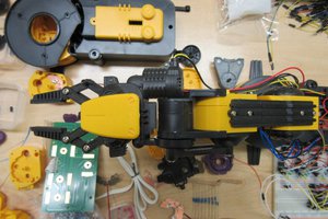
So, let's start with the mechanical track part. It was an interesting challenge since we used the motors of the windshield wipers of the cars; These motors have a gear reduction mechanism, which at the cost of losing speed, gain a lot of force, are designed to be able to work in any condition, be it snow, sand, water. That is why they are quite efficient for this use. As a curious fact I can say that they could even carry the weight of my own body (72 kg or 158 pounds), I would think that they have the capacity to support double the weight of each of the motors working together, and I say motors because we use 2, not We wanted to complicate ourselves with no rare mechanism on the part of the mechanical tracks, just two motors that would work together, that would be able to go forward, backward, left or right.
It was simple to use motorcycle chains so that together with two sprockets per caterpillar, of which, one of them would be directly connected to the motor which would produce the corresponding movement. No other compliation with that part, the problem would come with electronics, how to control the direction of rotation of such robust motors that consume as much current as these? The answer was to use relays, which can handle considerable currents, and without a doubt, they were going to be able to spare with such heavy work.
So, in order to obtain the greatest robustness and simplicity possible, we made 2 boards, one for control and the other for power, the idea was to use an H bridge called L293D in the first stage, which, according to input signals, is capable of control 4 outputs, 2 for each motor respectively, where, depending on the aforementioned inputs, you could reverse the direction of current at the outputs. After that, optocouplers would perform the job of electromagnetically isolating and protecting said component (L293D) and also the robot's brain where the PIC16F887 would be and the outputs that control the entire system, which are 6. 3 for each motor where, looking at the datasheet of the L293D we can understand that for example, if we wanted to turn the motor to the left, we should enable the left input, disable the right turn input and an input that would always be enabled in our case, which is the PWM, We will not control the speed of the motor this time since it is very low by itself so it would not be necessary, we will only use the maximum speed of the motor.
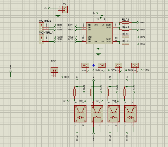
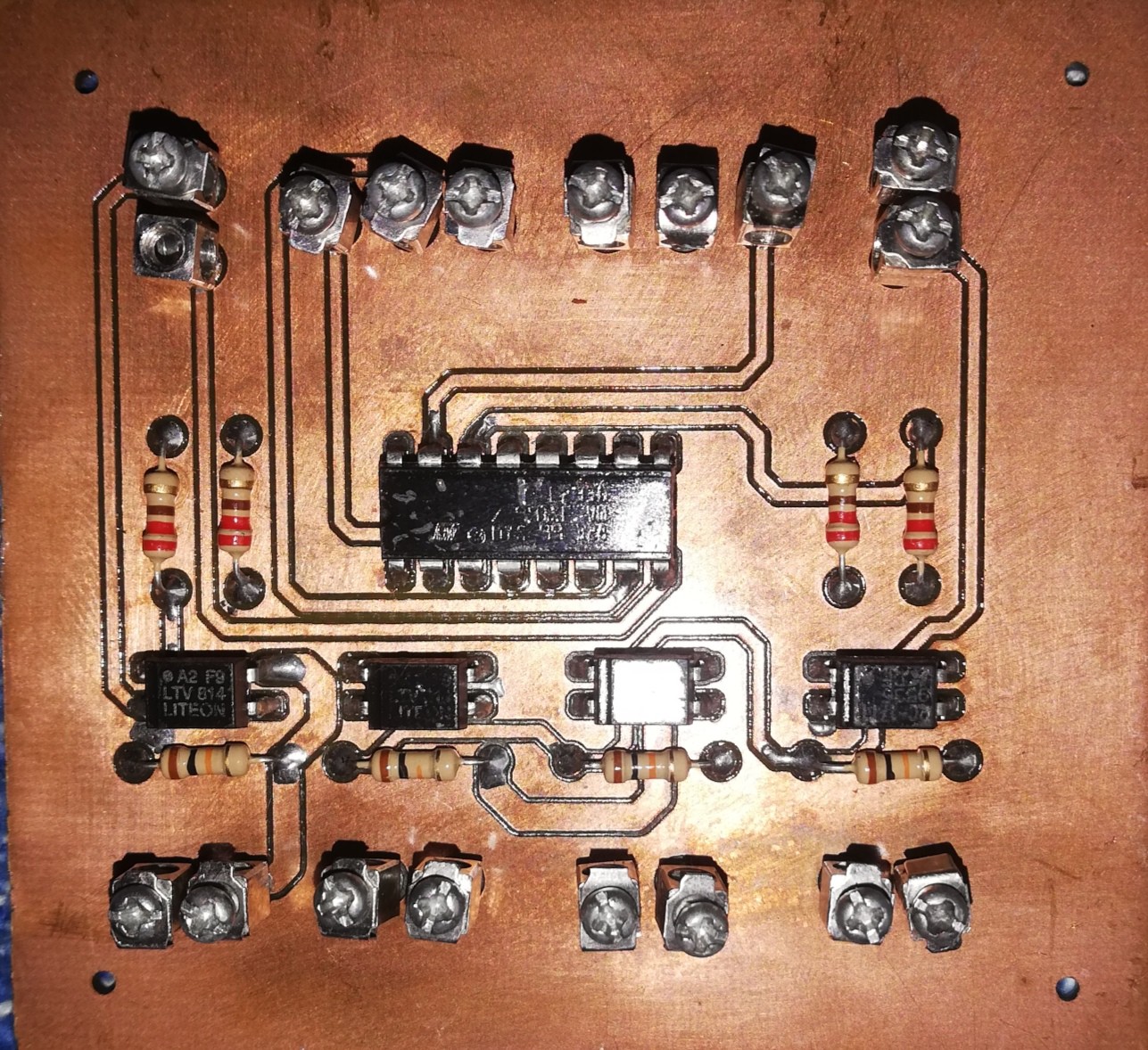
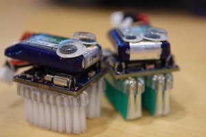
MCTRL A and B are the two inputs that the component has, and the outputs are already 4 that we can see after the optocouplers. The end result of the control board is this:
The programming is quite simple, pure if and else conditions, where depending on the input we have in the receiving PIC or brain that would be inside the robot, it would order the L293D to work. So as I explained previously, for example, if we wanted to move...
Read more »
 Steven Kibler
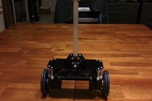
 Kenji Larsen