 Craig
CraigThe SBC-85 cassette tape interface has the default SBC-85 form factor and can use the SID and SOD lines off the backplane. However, for most systems those lines are busy with the serial port onboard the CPU so there is also a connection using the standard SBC-85 I/O 26 pin header. Unfortunately, this requires one input pin so, if using the 8155 I/O connector, it needs to occupy one bit of an input port and at least one bit of an output port. There are three additional software controlled LEDs to give status to the user such as adjusting volume or whatever the programmer sees most suitable.
The nicest thing about the Intel interface in general, and this board in particular, is that they are bone simple. Intel was all about reliability so they picked the simplest encoding scheme they could imagine that would be immune to all the crap a cassette player did to the information. In the Intel scheme, they break each bit into three segments. The first segment is always a tone burst, the last segment is always a pause (silence), and the middle segment held the data. In practice, to receive data the interface simply waits for a tone burst to announcing the beginning of a bit, determine the value of the data bit, and then wait for the next tone burst. Since each bit began with a tone and ended with a space, the bits were distinctly separated from one another making it easy to know when a bit started and ended no matter the tape speed. The CPU itself was used to create the tone bursts during write (e.g., 2kHz bursts) and to decode the bits during read. Decoding the bits is extremely simple, straightforward, and immune from most tape distortions. Given that each bit started with a tone burst and ended with a space, given just those two the bit time would have a 50% duty cycle, i.e., one burst, one space. So the data bit will either change the overall bit duty cycle up to 2/3 when the bit is 1, or down to 1/3 when the bit is a zero. It does not take a very sophisticated decoding routine to separate a 33% duty cycle from a 66% duty cycle. In practice, during receiving mode the software sets a counter to zero and then begins polling the input at a fixed rate during each bit. If it polls a logic one it increments a counter. If it polls a logic zero it decrements the counter. At the end of the bit the count will be, ideally, be 33% of the total counts above zero or 33% of the counts below zero. It is much easier to simply put zero as the deciding point so the sign of the counter shows if the bit was a one or a zero.
In the end, the code to write and read tape is straightforward and, so far, pretty robust.
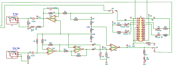
Since the CPU is doing all the timing for data writing and all the discriminating for data reading, the circuit can be extremely simple. The circuit is based around a quad op-amp with one op-amp serving as an output driver that buffers the signal from 0-5V logic to +/- 1V. The input circuit is not much more complicated with one amp as the input buffer whose output is inverted by op-amp #3. The natural and inverted signals are then summed using diodes and the integrated sum going to the fourth op-amp which is a comparator to generate a TTL signal. All totaled, the circuit takes one LM324 quad op amp, a dozen resistors, and a few capacitors.


 Anders Dinsen
 Jac Goudsmit
 Eric Ljungquist
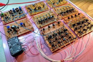
 matseng
Mate, you might want to look at how the Sinclair Spectrum did tapes. It was the fastest 8-bit tape loader / saver I'm aware of, could load 48K in about 4 minutes.
Basically it was header first, containing data about the data, then data.
It went
Tone burst, Header (about 1 second long, containing name, load address, etc)
pause for a second
tone burst, 4 minutes of data
Encoding was done by pulse length. Long pulse for 1, short for 0, say. Might be other way round, doesn't matter. The hardware was pretty much just a zero-crossing detector connected to the tape player. With that you can measure pulse length, and it doesn't matter if the pulses are inverted by the tape player, or smoothed out into rough sine waves.
All done in software. CPU reads the zero-crosser for the first edge, then starts counting. Upon recieving the next edge, it checks the count for long or short. Then carry on!
The tone burst helped give an idea of what sort of pulse length to expect, what with tape stretching and the like.
The Spectrum's ROM was famously disassembled in a book (The Complete Spectrum ROM Disassembly) which annotated all the functions. Might be a help, and will certainly reduce thumb-twiddling time. ONE BIT at a time!? Were Intel insane!? Well, looking at the 8086...
If you chose Intel's horrible slow format for historical reasons, fair enough, ignore this. It's just that Sinclair achieved the fastest, simplest, cheapest tape access in 1982 in software, and I like to spread that knowledge.