After waiting for some further parts, we have now begun to assemble and test a simplified version of the breathing circuit. The real breathing circuit will include a hookup to an oxygen supply, check valves to manage the inspiratory and expiratory paths, virus filters, and a humidifier/heater. For this testing, we are mainly focused on a few goals:
- Testing basic motor control
- Basic control of speed and interfacing with the motor
- Implementation of pressure controller
- Testing pressure sensor feedback effectiveness
- Implementation and testing of flow sensor for tidal volume measurement
INITIAL MOTOR CONTROL
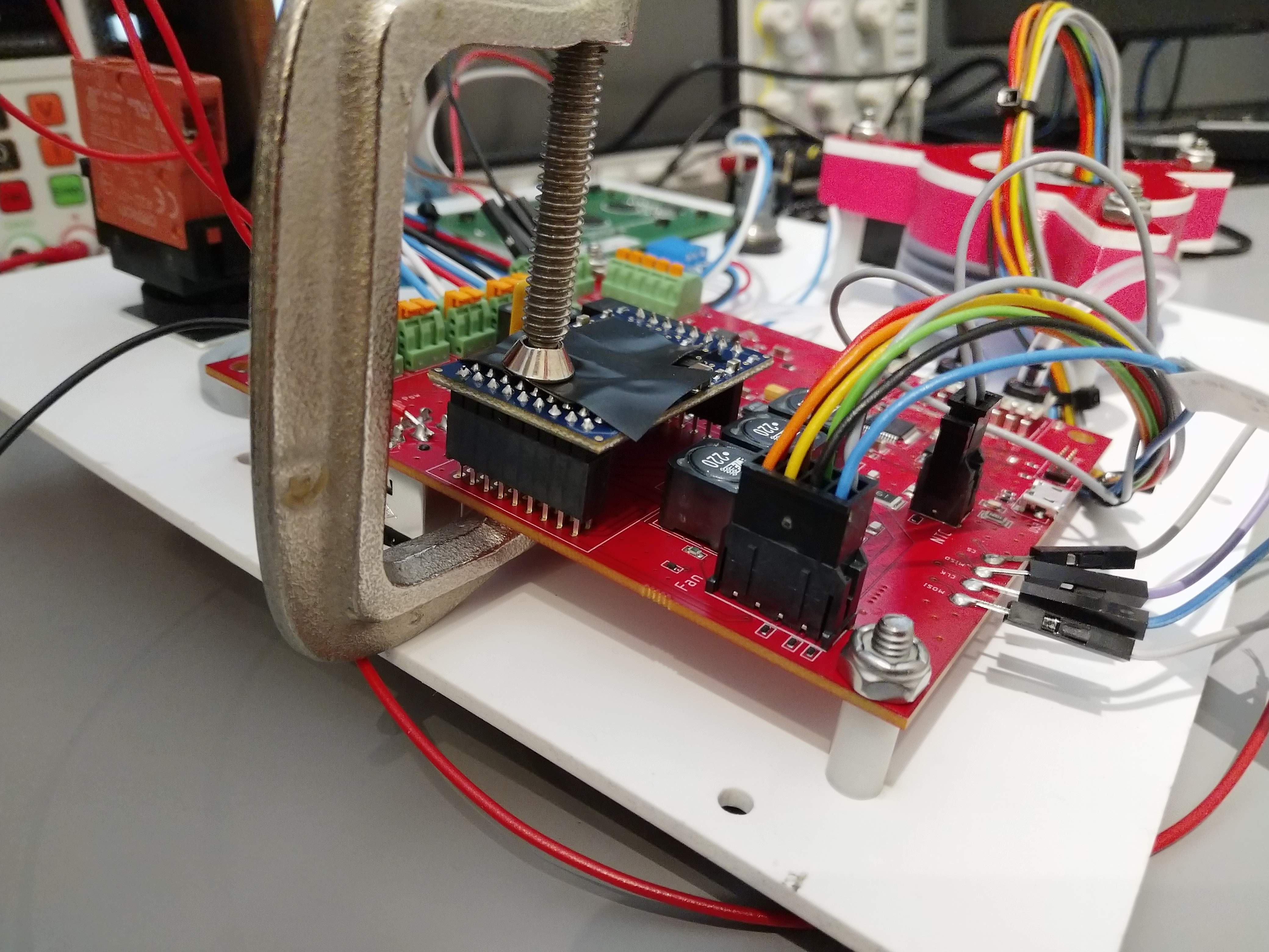
The main challenge to initially implementing motor control was a PCB design mistake related to the mounting of the brushless motor controller module. The design called for female header pins to be soldered onto our PCB and act as a socket for the module. Unfortunately, the drill size for all of the pads was too small, and the header pins would not fit through. We looked for alternative headers with smaller diameter pins, but were not successful. Ultimately, we ended up soldering the header pins "on top" of the pads, using the holes as alignment detents. With a few dozen pins, we figured it would be structurally sound enough for testing, and we could solder enough to be electrically OK. The picture below shows the controller module clamped in place in preparation for soldering it down.
The design called for Maxon's 380200 OEM brushless motor controller module. During original research, we had purchased an alternative from Anaheim Automation. While mostly pin-compatible, it was somewhat different. In particular, we used Maxon's controller in closed loop speed control mode, but the Anaheim Automation part was open loop only. In addition, the maximum speed of the Anaheim Automation part was not clear. This resulted in some issues.
During initial testing, things seemed OK. The pressure controller that we had designed was a PIDF controller. A trapezoidal pressure profile was generated based on the ventilator settings, and the controller would attempt to track measured pressure to that profile. The controller source can be seen below.
/*
 *    \brief Performs PIDF control
 *
 *    Has integral error range and anti-windup
 *    Has derivative filtering
 *    Note: this is a tracking controller, so "derivative" can somewhat abruptly change, need to be careful
 *
 *    \param control Pointer to the control structure defining the pressure profile
 *    \param params Pointer to the structure holding controller tuning parameters
 */
 static float pidf_control(lcv_control_t * control, controller_param_t * params)
 {
    static float error_integral = 0.0;
    static float error_derivative = 0.0;
    static float last_error = 0.0;

    float error = control->pressure_set_point_cm_h20 - control->pressure_current_cm_h20;

    float alpha = 0.7;
    error_derivative = alpha*(error-last_error) + (1.0 - alpha)*error_derivative;

    if(abs(error) < params->integral_enable_error_range)
    {
        error_integral += error;
        if(abs(error_integral * params->ki) > params->integral_antiwindup)
        {
            error_integral    = (error_integral/abs(error_integral)) * (params->integral_antiwindup) / params->ki;
        }
    }
    else
    {
        error_integral = 0.0;
    }

    float output = params->kf * control->pressure_set_point_cm_h20 +
                    params->kp * error +
                    params->ki * error_integral +
                    params->kd * error_derivative;

    if(output > params->max_output)
    {
        output = params->max_output;
    }

    if(output < params->min_output)
    {
        output = params->min_output;
    }

    last_error = error;
    return output;
 }
For testing of the code originally, we had set it up to have only non-zero feedforward gain. The motor controller modules are controlled with an analog signal from the MCU's DAC. In other words, the MCU was initially outputting a voltage linearly proportional to the desired control pressure. I could then look at that signal on the scope to ensure the trapezoidal pressure profile was being properly generated. For initial motor testing, the controller was left this way, and the motor spun up and slowed down appropriately.
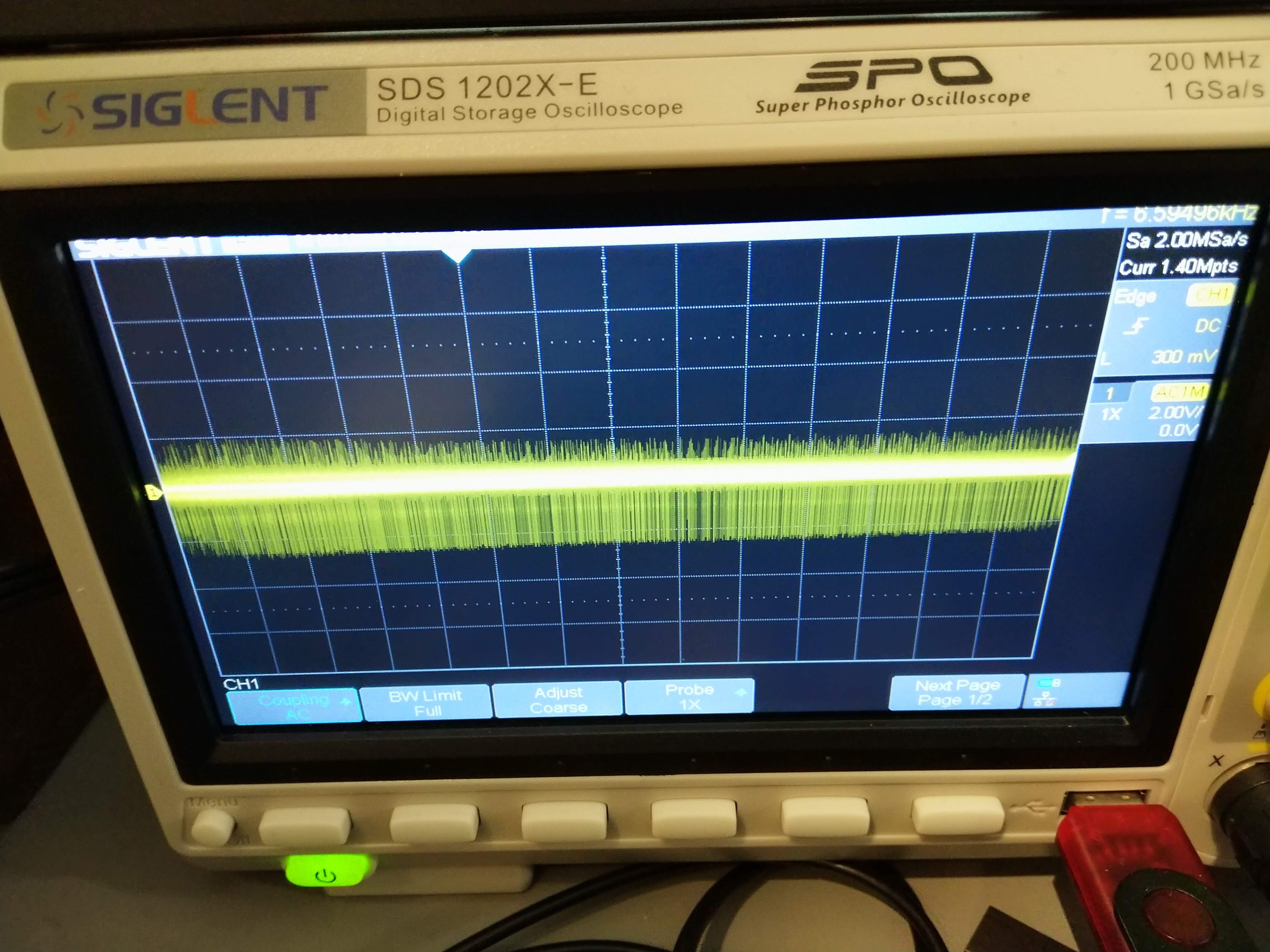
However, as I began to tune the controller, issues arose. I discovered an odd issue where if I increased control gains a small amount, the motor would twitch slightly, and the whole system would reset. The symptoms seemed to indicate a power issue. Indeed, it turned out the instantaneous control effort would be increased enough to cause noise on the power rails that would reset the system. This was of course, very concerning, but odd since we had followed the recommended design for Maxon's motor controller. By heavily filtering the motor command, the system could avoid such spikes, with reduced ability to track. The image below shows the 24V power rail, AC coupled, when the motor was started. Clearly there is a lot of noise.
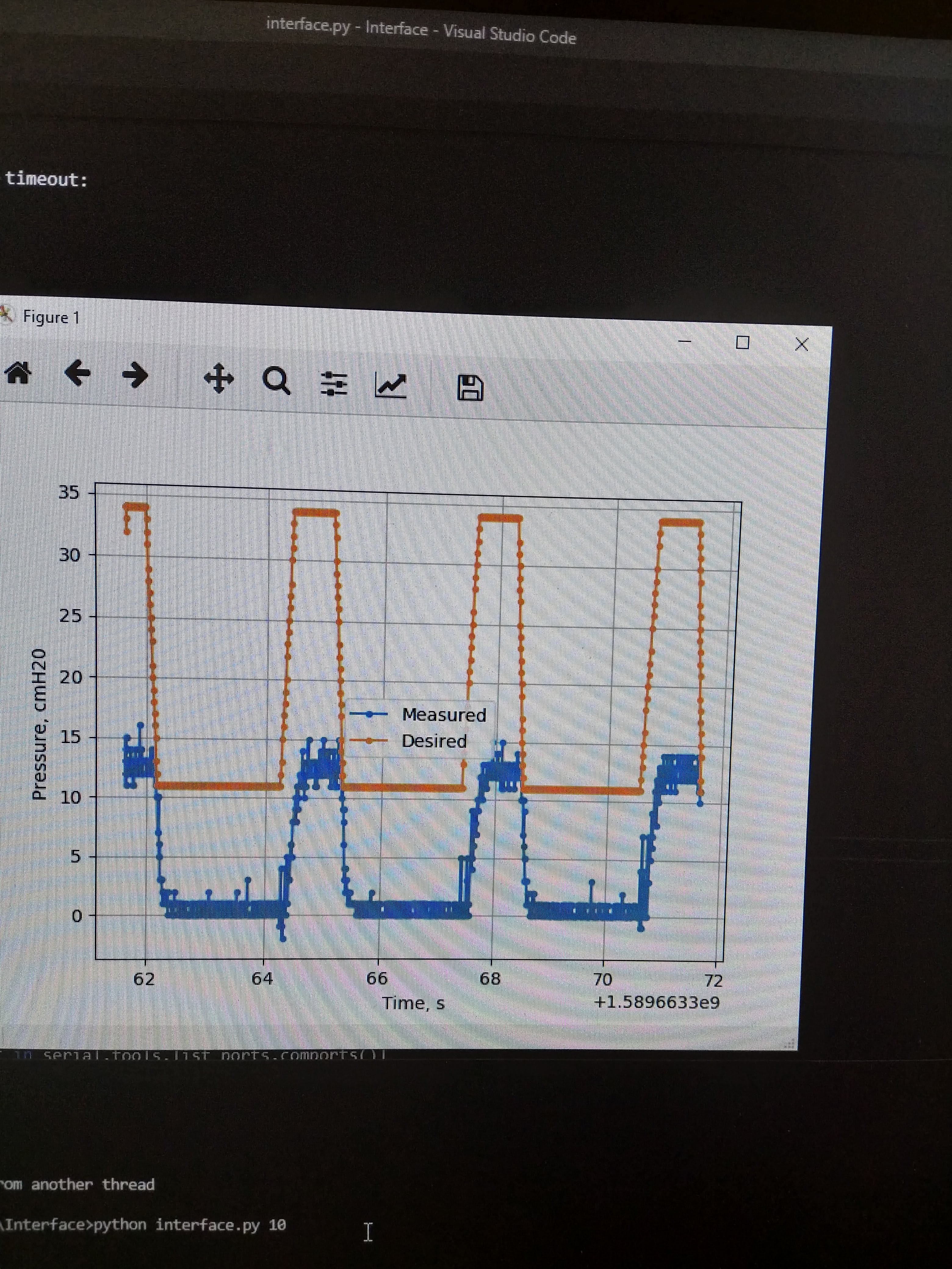
However, we also discovered another issue: the system was not able to reach high enough pressure. I built a Python interface to communicate with the ventilator over USB so the controller could be tuned. On one test with the original Anaheim Automation speed controller, the following pressure profile was seen (pardon the picture of a screen.) The lag is clear (and will be discussed later), but also the peak measured pressure was only about 12 cmH2O, far too low to be useful. We bought the Maxon speed controller to see if these issues would be resolved.
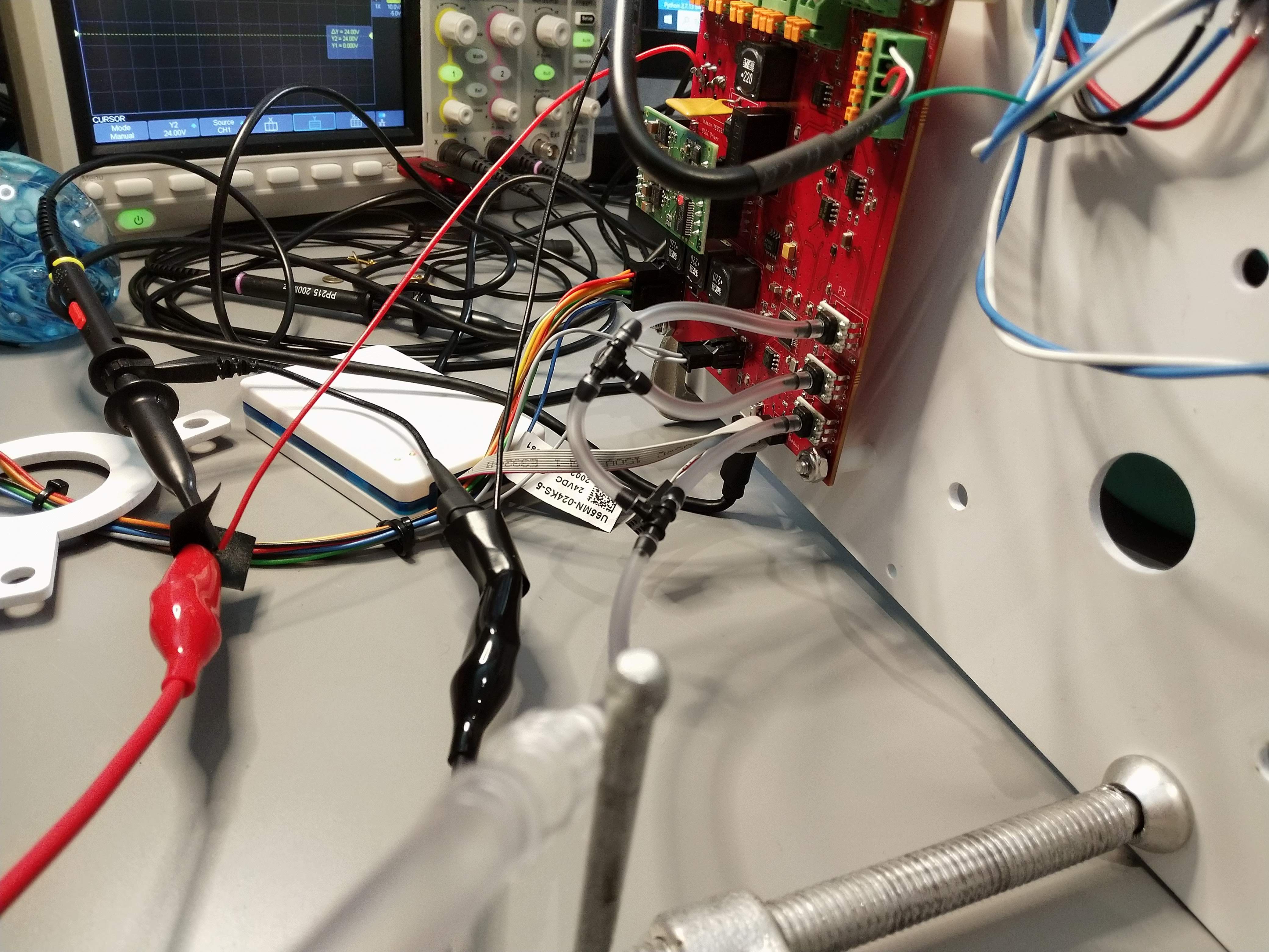
The Maxon speed controller instantly showed major improvements. Control parameters that previously would have caused a reset, no longer did. The peak pressure also substantially increased. In preparation for more detailed controller tuning, I set up the air circuit to use all three pressure sensors, with appropriate averaging, outlier detection, and filtering. The image below shows all three sensors connected to the patient circuit.
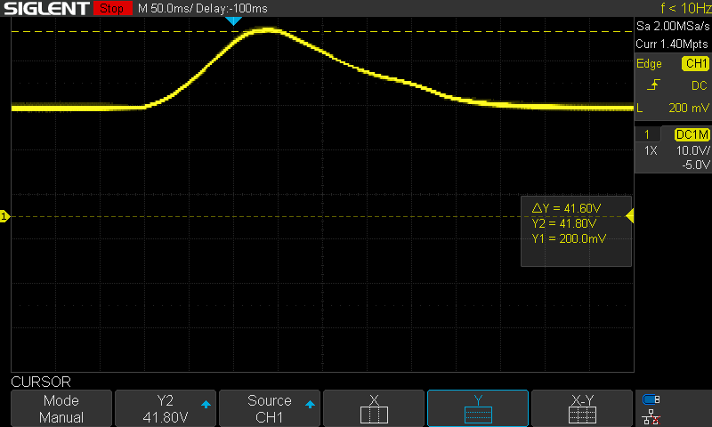
Unfortunately, the issues were not all gone. While the system would no longer reset when spinning up the blower, if it was spun down too fast the system would reset. While connected to 24V power from my switching lab bench PSU, I watched the voltage on the scope as the motor would turn off in these situations. The spike was much smoother and higher than I expected. The voltage spiked up to about 42V over about 350ms. I am actually surprised this did not (at least noticeably) damage other parts. Oddly, with minor re-tuning so that the controller ramps down more slowly, no spike at all is seen.
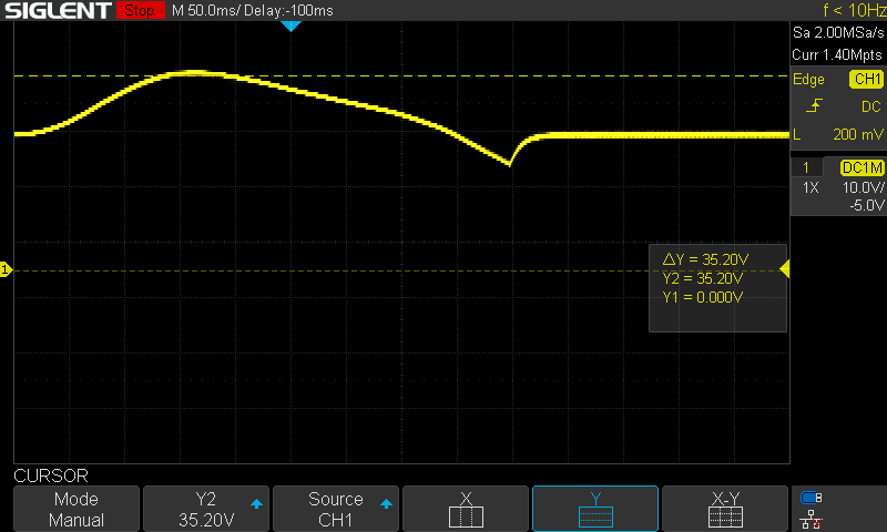
I was concerned that this could be a power supply issue potentially. Perhaps the dynamics of the motor was negatively interacting with the switching controller of my PSU. I therefore powered the system using its intended medical grade AC-DC power brick. The same issue was seen, although the profile of the spike is different. The spike was up to 35V, with a dip afterwards.
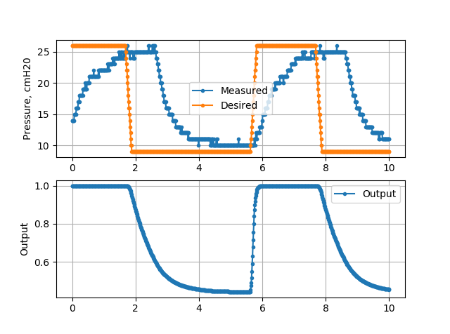
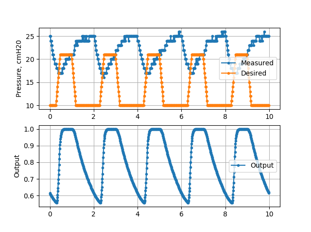
The best solution to this problem is still unknown, but since the motor ramp up is no longer an issue, I changed the command filtering based on whether the command is increasing or decreasing. It can now ramp up much faster than it can ramp down. For rather slow breathing settings, the profile is shown below. As can be seen here, the maximum pressure is now about 25 cmH20. Although the command ramps up rapidly to full effort (1.0), the pressure increases fairly slowly. Indeed, the pressure rise time constant appears fairly similar to the ramp down. It is not clear yet why this is. Perhaps the closed loop speed control on the Maxon motor is limiting this.
Significant lag from command change to measured pressure change is also visible here. For a pressure control system, this is not unexpected. We are compressing air, and must wait for the wave to propagate through the system to the sensor. For simple PIDF controllers, pure lag can be destabilizing, so we must be careful. For example, the below image shows a pure proportional controller. The lag induces undesirable oscillations. It is not unstable, but indicates the challenge.
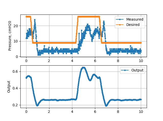
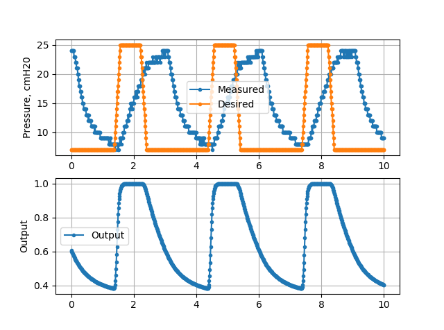
The slow pressure response becomes a challenge for faster breathing settings. The image below is set to 30 breaths per minute with a PF controller. Regardless of poor tuning, the pressure clearly does not decay fast enough to reach a steady state before the next inhalation begins.
For 20 breaths per minute, we can get a bit better, but the lag is still a major challenge. We are clearly not creating the desired trapezoidal pressure profile.
Tidal Volume Estimation
In addition to pressure control, our ventilator provides tidal volume monitoring using integrated measurements from a mass flow sensor. We have tested the Sensirion SFM3300 sensor previously, and it seemed to work well. However, it is out of stock everywhere. We therefore designed for the Siargo FS6122 sensor, which has thousands in stock. The specifications are quite similar, but the I2C interface is different. We set up this sensor on its own SERCOM I2C, and wrote the interface to be fully interrupt driven and non-blocking. Since we are measuring tidal volume by integrating flow rate, drift is expected. We therefore want to reset the estimation at each cycle, and not track over a long time. The currently implemented algorithm is simple and a work in progress but does work most of the time. It detects flow transitions from in to out and out to in (filtered and with hysteresis to reduce failures), and uses those transitions to estimate each cycle. Once we better understand the lag in the system, we can also use the controller information to determine each cycle. For now, however, it seems to work. The video below shows a few cycles into a rough dummy lung consisting of an elastic bag with weight on top. Note this setup is not intended to be a realistic lung, but rather provide some resistance to the flow so the tidal volume estimator can be tested. It is quite consistent.
Discussions
Become a Hackaday.io Member
Create an account to leave a comment. Already have an account? Log In.