 Mark Rehorst
If you use a "normal" screw, say M5, one turn of the screw will move the bed 800 um- that's 4 typical print layers. That makes it very hard to make the fine adjustments <50 um that are typically needed.
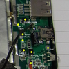
In this project, a differential screw is used to make a finely adjustable, Z=0, optical endstop for a 3D printer. The differential screw is made by turning the end of an M5x0.8 screw down to 4 mm on a lathe and threading that portion with M4x0.7 mm threads. When the screw is turned 1 full revolution, the screw moves 0.8 mm, meanwhile, the nut on the M4 portion of the screw will move 0.7 mm in the opposite direction relative to the screw. The net movement of the M4 nut/flag that interrupts the light beam is 100 um in the same direction as the screw is moving. Using a thumbwheel with 10 bumps (so 10 um each) allows easy small adjustments of the printer's bed position.
I used a 5mm thick piece of teflon for the fixed nut for the M5 portion of the screw, and a standard M4 nut for the other part of the screw. The M4 nut is embedded in the printed flag, and the flag/nut moves in a printed square tube that prevents them from rotating. A spring inside the tube keeps the M4 nut's threads engaged and prevents backlash.
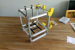
The overall adjustment range is only about 2 mm, but that's more than enough as the opto endstop mounts on the t-slot frame of the printer and can easily be repositioned within the range of the differential screw adjuster.
More details here: https://drmrehorst.blogspot.com/2020/03/a-new-z-axis-optical-endstop-design-for.html


 Cees Meijer
 Sl_Postmann
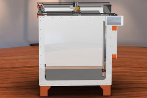
 Dmitry Shevchenko
 Leo Vu
Hey Mark, thanks for sharing. This is a great way to make a finely tuned adjustment. It checks all the right boxes to on simplicity, cost, executability (if that's a word) and real world results. There's multiple ways of connecting the different size and pitch bolts so just putting it out there with your well worded & explained details with the corresponding pics is a godsend for a lot of people. Great thinking if you figured it out, if not great research and great articulate post. Thanks again!