 Samuel A. Falvo II
I have been thinking about how to reliably solder the surface-mount pin headers to the TinyFPGA BX module for some time now. I think I've come across a solution.
- Solder on the 14-pin outer/through-hole connectors. It’s important that they be soldered for mechanical stability in later steps.
- Insert two pins of the surface-mount pin header into female strip socket.
- Insert the female strip socket cross-wise on the TinyFPGA’s through-hole pins.
- Insert another strip socket a few pins away to lock in the registration.
- Now you can solder the ends of the surface-mount connector to the board with full confidence that they’ll line up correctly with the socket on the PCB.
- Scoot the cross-wise sockets down, and solder the other end of the surface mount socket.
- Now you can remove the cross-wise sockets, and solder the remaining pins.
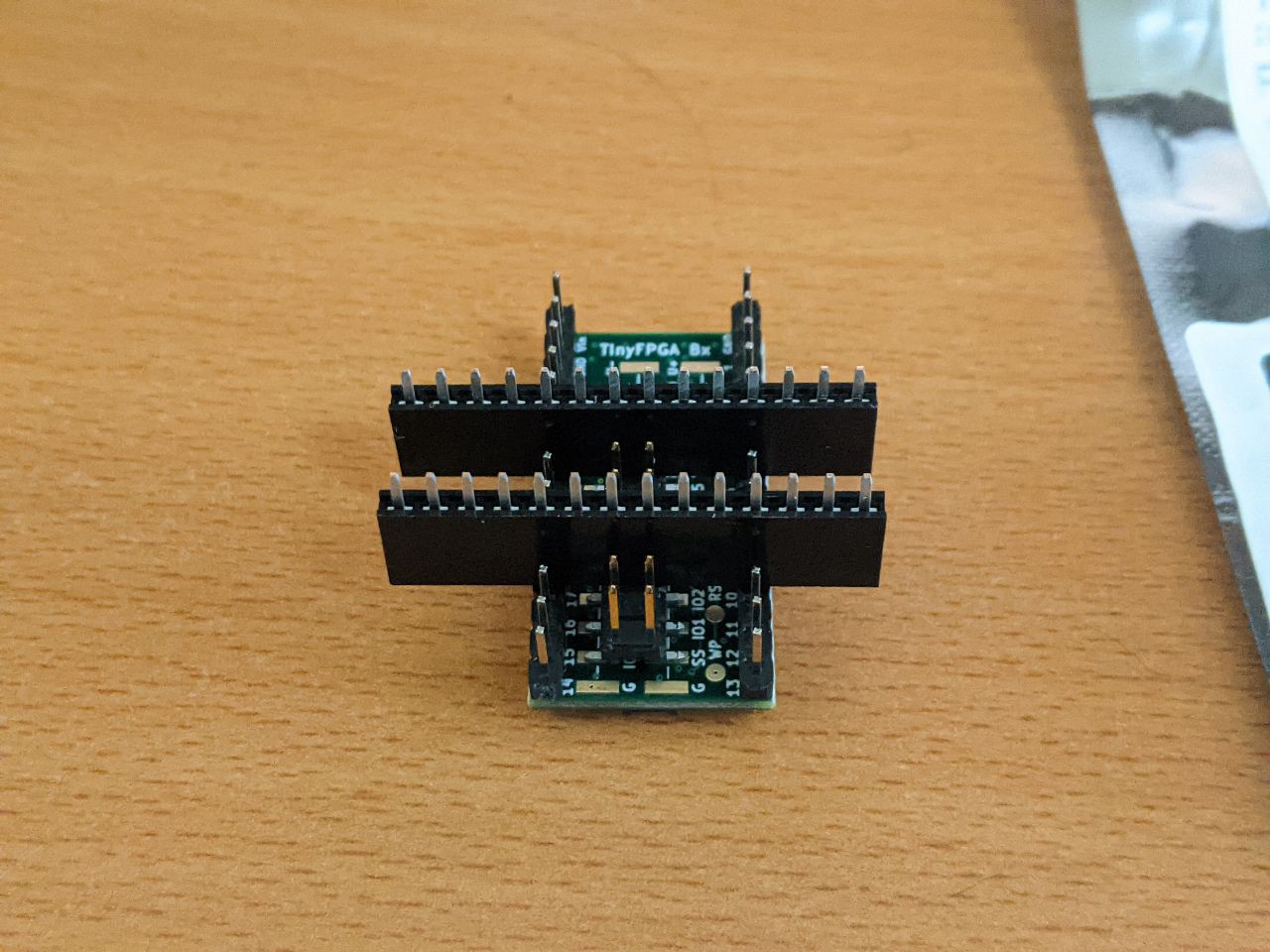
Here's a picture of a mock-up which demonstrates what the arrangement should look like after step 4, but before the completion of step 5.
Discussions
Become a Hackaday.io Member
Create an account to leave a comment. Already have an account? Log In.