The goal of this task is to prototype the solution using a micro-controller to validate the concept
The Arduino prototype
An Arduino Uno did not really match the minimum hardware philosophy, but I had nothing less fancy to try it on. And the focus was on making sure it worked on the micro-controller in order to move on to the next task.
The prototype was set up to detect 3 digits from the minimum sensor model below.
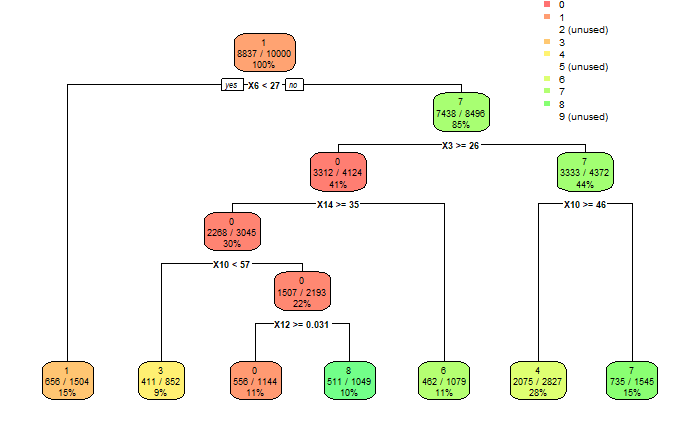 The digits to be detected were "1", "4" and "7", using a total of 3 LDR sensors for pixels 3, 6 and 10.
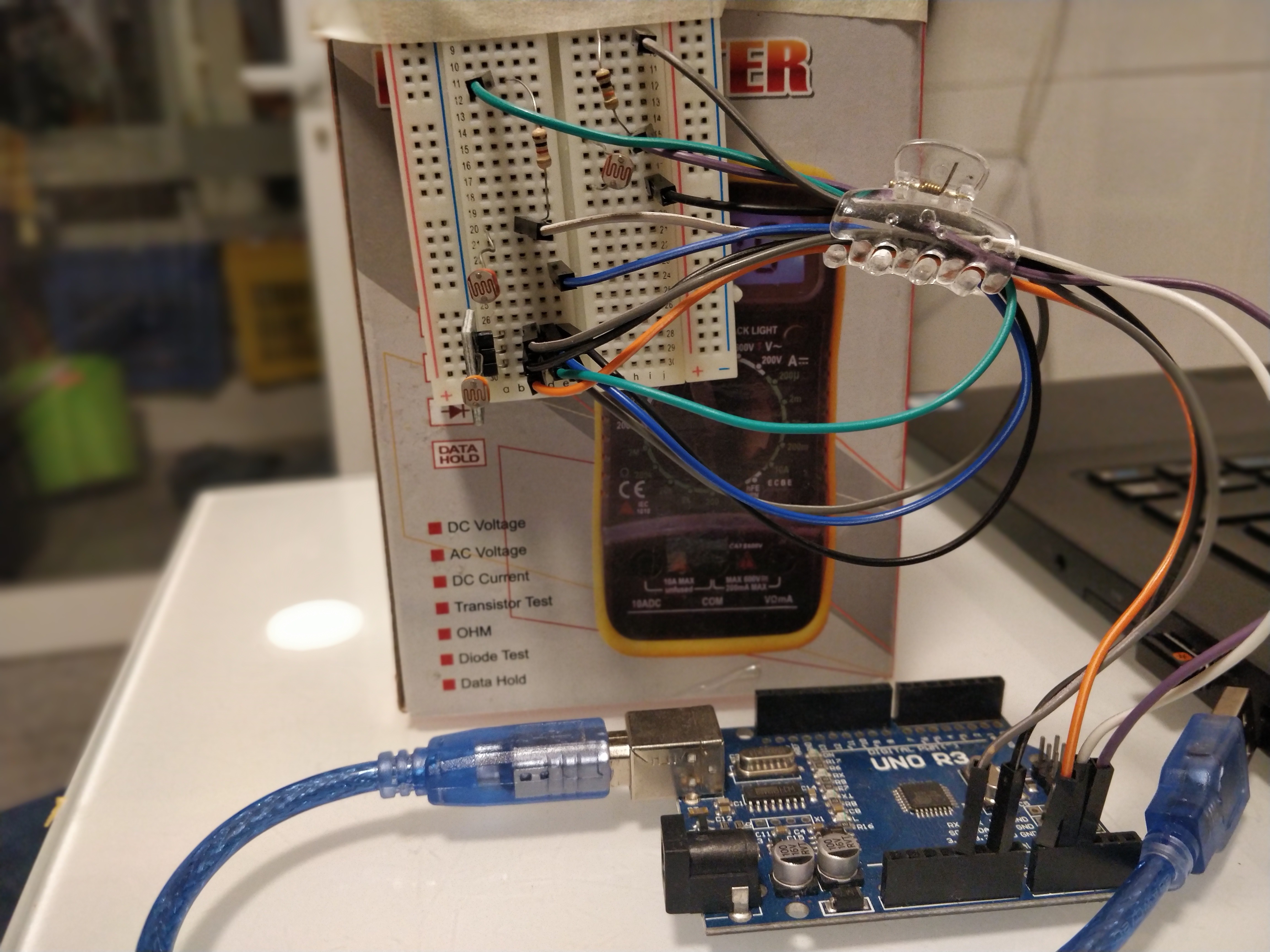
The set-up worked as follows:
- Each LDR was a part of a voltage divider with a 10 k.ohm resistor.
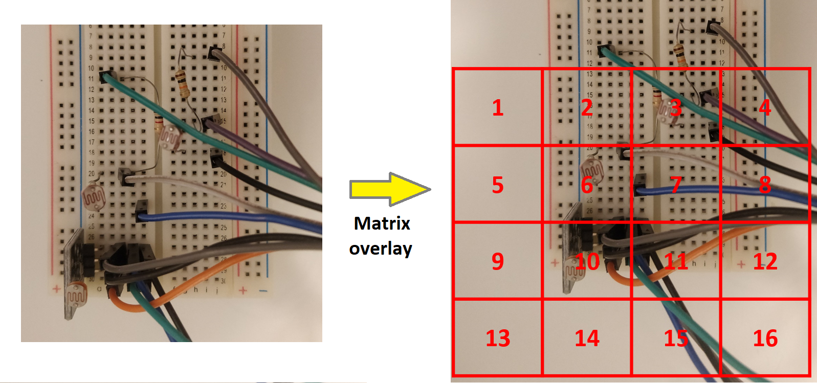
- The LDRs were of 14 k.ohm (pixel 10), 40 k.ohm (pixel 6) and 60 k.ohm (pixel 3).
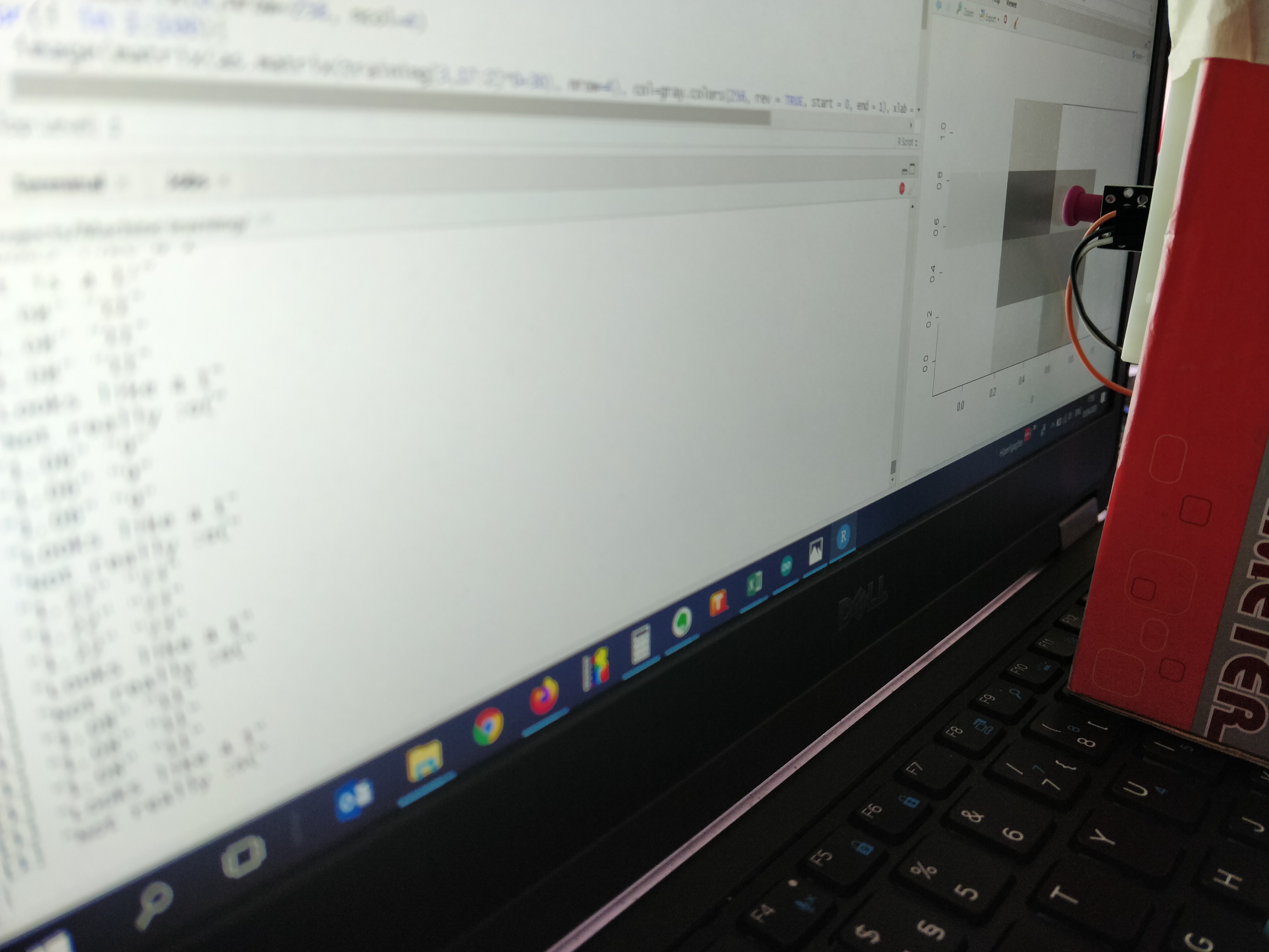
- The sensors were aligned with the matrix on the screen in order to capture the the analog output on each pixel.
- The matrix representing the number was drawn on the screen of a laptop using Rstudio.
- The response of the LDRs was calibrated using an intensity sweep before each test.
- The resulting voltage was read via the ADC on the Arduino on pins A0, A1 and A2 and 3 simple if-then loops represented the splits on the Decision tree.
- Both voltage and likelihood of a number being identified was print()ed to the serial monitor.
The matrix was drawn on the screen and cycled trough the dataset.
Finally, the jig was placed in front of the screen. Both displayed digit and detected digit were recorded and filled a confusion matrix to verify the accuracy of the setup.
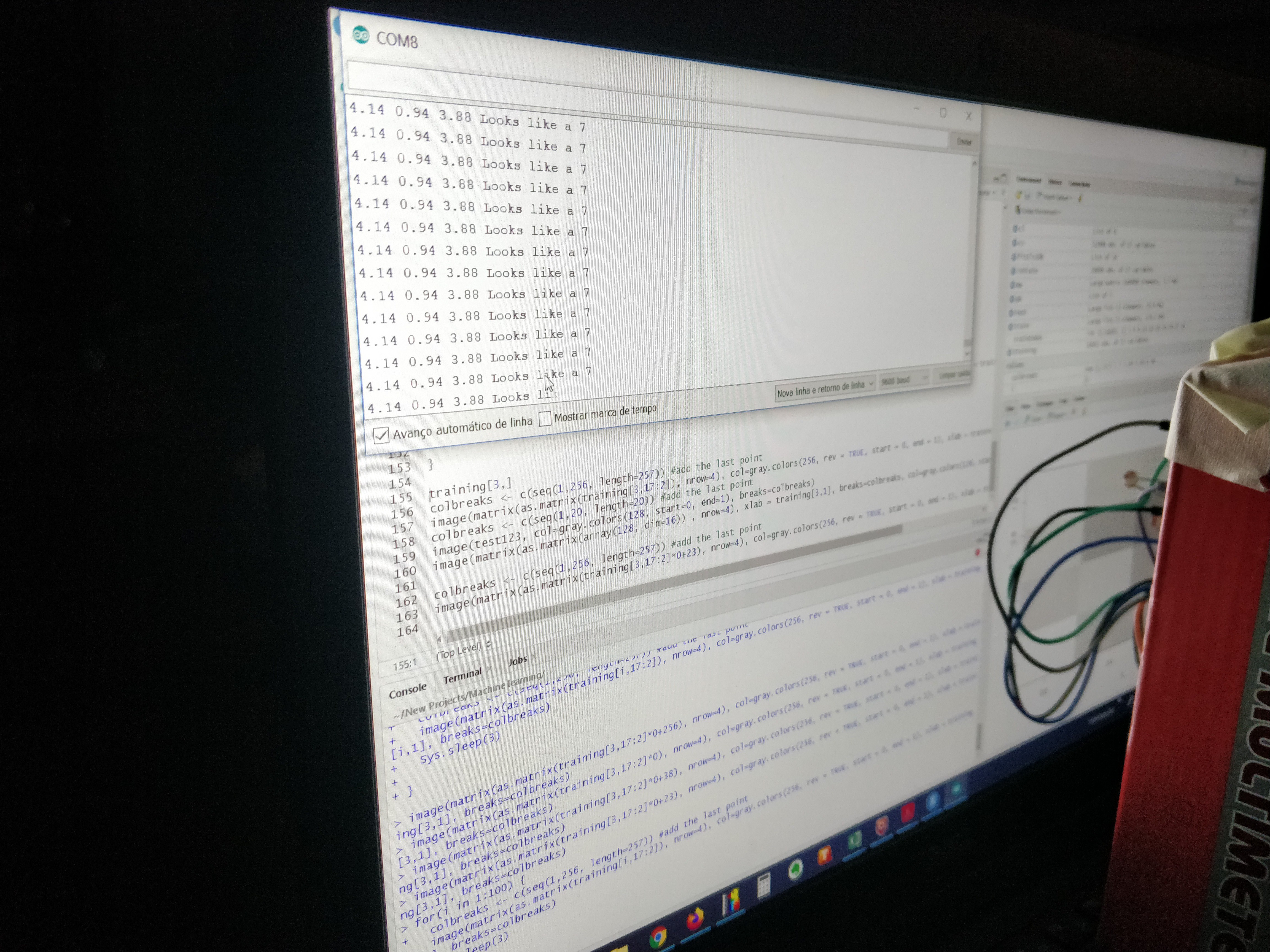
In the end, the setup worked as expected, with the numbers 1, 4 and 7 being identified, sometimes.The accuracy, nevertheless, was appalling.
All in all, it was mighty difficult to get a consistent reading out of anything other than digit "1". And of course that depends on your definition of consistent.
Below is the confusion matrix for the prototype. Columns denote the number shown, rows the number identified by the decision tree. Note that if it was not a 1, 4 or 7, the model was set up to classify everything else as a 0.
      [,1] [,2] [,3] [,4] [,5] [,6] [,7] [,8] [,9]  [,0]
 [1,]   15    1    5    6    1    2    3    0    4     0
 [2,]    0    0    0    0    0    0    0    0    0     0
 [3,]    0    0    0    0    0    0    0    0    0     0
 [4,]    5    1    1    3    5    0    6    0    5     0
 [5,]    0    0    0    0    0    0    0    0    0     0
 [6,]    0    0    0    0    0    0    0    0    0     0
 [7,]    3    9    1    7    2    8    0    6    3     0
 [8,]    0    0    0    0    0    0    0    0    0     0
 [9,]    0    0    0    0    0    0    0    0    0     0
 [0,]    0    0    0    2    2    0    2    0    4     0
The accuracy of digit 1 is just over 33%. For number 4, it's 7 % and for number 7, well, not a single 7 was identified correctly.
It was well short of the accuracy I was expecting to obtain with the setup so a bit of troubleshooting was in order.
Debugging
Cross-talk
In order to verify whether there was any issues with the intensity of neighboring cells on the matrix affecting the reading of the sensors, the setup was modified using a molding balloon cut to length in order to shield the sensors from light coming from the sides.
The resulting setup with the protected sensors is shown below.
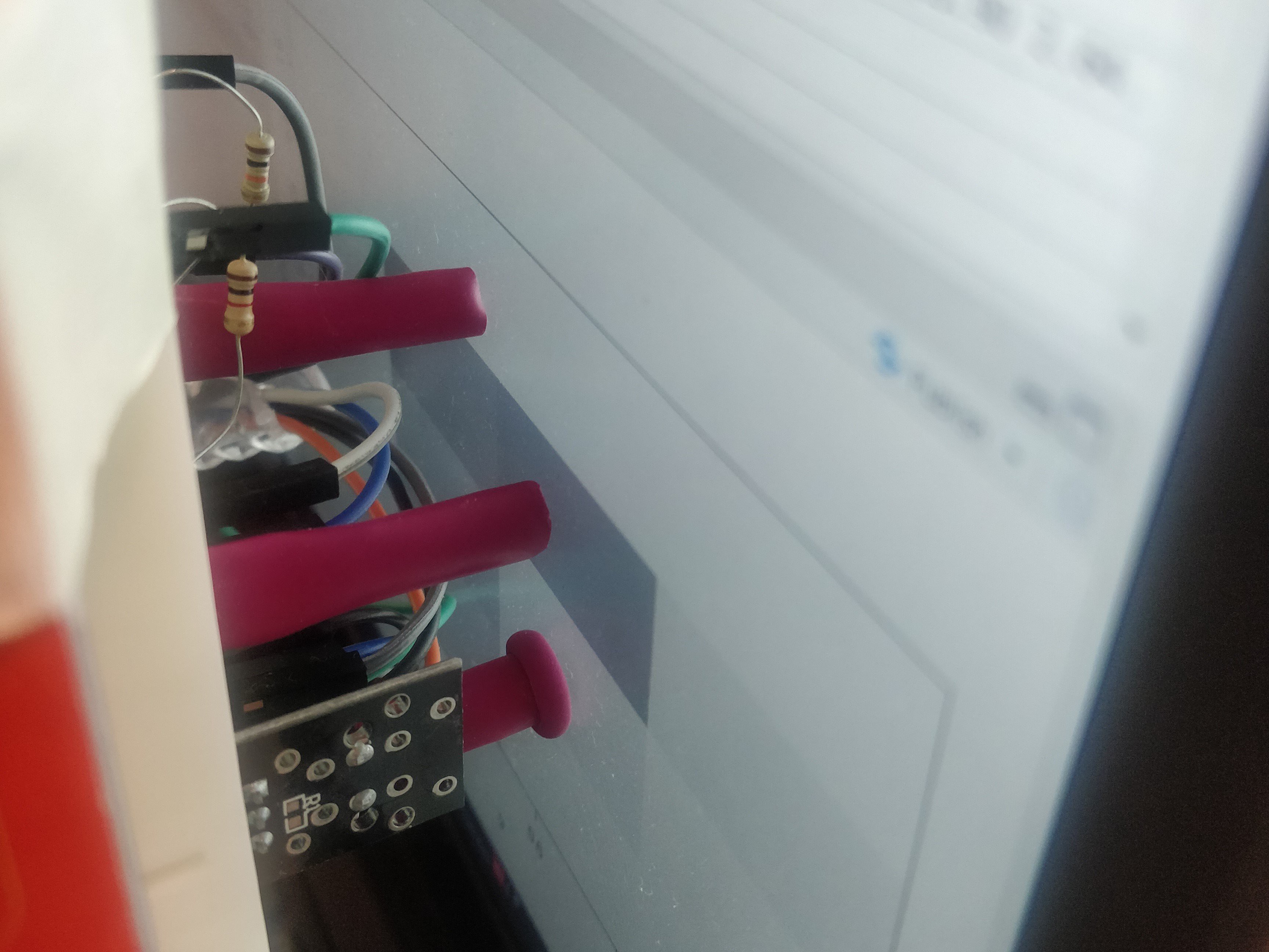
There was no significant difference in the overall accuracy, so this was not really what was causing havoc in the system.
Sensor accuracy
The decision tree splits happened at very low intensity values for these sensors, i.e. the sensors needed to measure values very close to the edge of their envelopes. The plot below shows the voltage versus intensity for all three sensors and the area where they'd be causing a split on the decision tree.
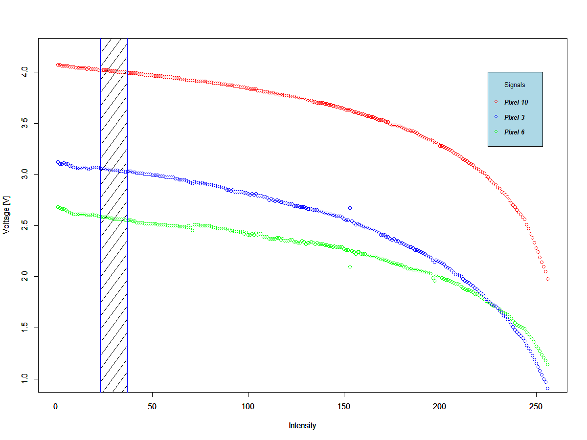
Even though the sensors are close the the edge of the envelope, there's plenty of measurement real estate available. This was probably not the cause for the accuracy issue but the plot shows that there was some jitter in the signal which is shown as deviations in the measurements, but only in some sensors.
Time series
Finally, it was time to check whether the sensors could be drifting with time. The plot below shows consecutive reads of a fixed intensity value during around one minute.
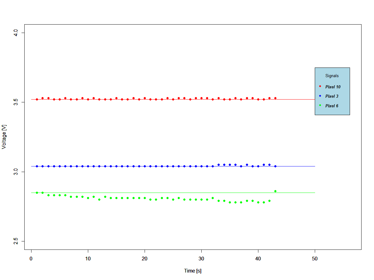
The sensor measuring pixel 6 shows a large tendency to drift. Since this sensor controls the first decision tree split, the whole system is compromised at the outset. Nevertheless, this could not be the main issue since pixel 6 controls the identification of digit 1, and this has the best accuracy of all digits being identified.
ADC crosstalk
Finally, I checked whether the signals were affecting each other on the ADC and bingo. There was a huge effect of the signals on one another.
After a long day of unsuccessful troubleshooting the ADC cross-talk on the Arduino UNO, it was decided to simply reduce the microcontroller prototype to the identification of a single digit, i.e. no signal to cross-talk to. This would allow me to use my time more productively on the second prototype using discrete components which was the goal of this project.
Single digit decision tree using Arduino UNO
The final setup consisted of a single split and a single sensor,.
It looked straightforward enough but two out of the tree LDRs could not complete the tests. This because the drift and jitter were so large that after a few images, they'd go off the scale and stop measuring completely.
          [,1] [,2] [,3] [,4] [,5] [,6] [,7] [,8] [,9] [,10]
 [1,]       17    9    4    1    1    0    1    0    0     0
 [Not 1,]   10   13   15   22   14   16   20   15   23     0
The theoretical accuracy for number one obtained in the Minimum Model task was 60 %, whereas the accuracy obtained in this test was a few decimal points above 40 %. The result obtained with the prototype was not as good as I was expecting but OK considering the poor repeatability of the LDRs.
Conclusion
The sensor choice proved to be unwise. They seemed to have a mind of their own and acted erratically at best.
The micro controller, in the hands of the inexperienced, could not rise to the challenge.
The model seemed to hold its own nevertheless despite the limitations.
The next challenge will be to turn this concept finally onto a discrete-component object recognition system.
Discussions
Become a Hackaday.io Member
Create an account to leave a comment. Already have an account? Log In.