 adria.junyent-ferre
I will explain this project step by step in the project updates. The roadmap is fairly simple:
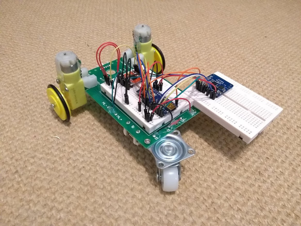
- Build a small Arduino-controlled autonomous turtle bot / robot car
- Implement BLE communications to be able to control the car from a phone/laptop/Raspberry Pi.
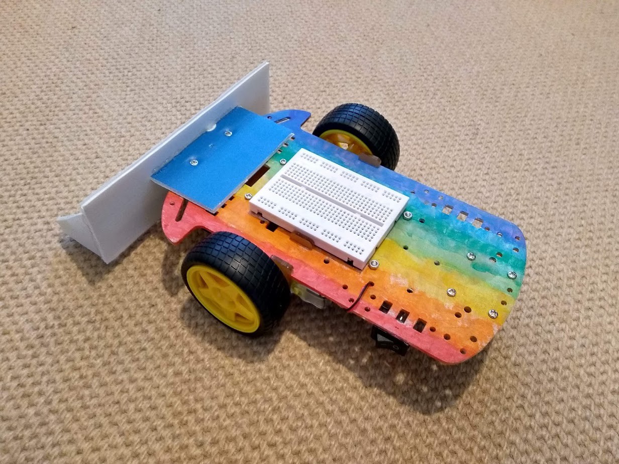
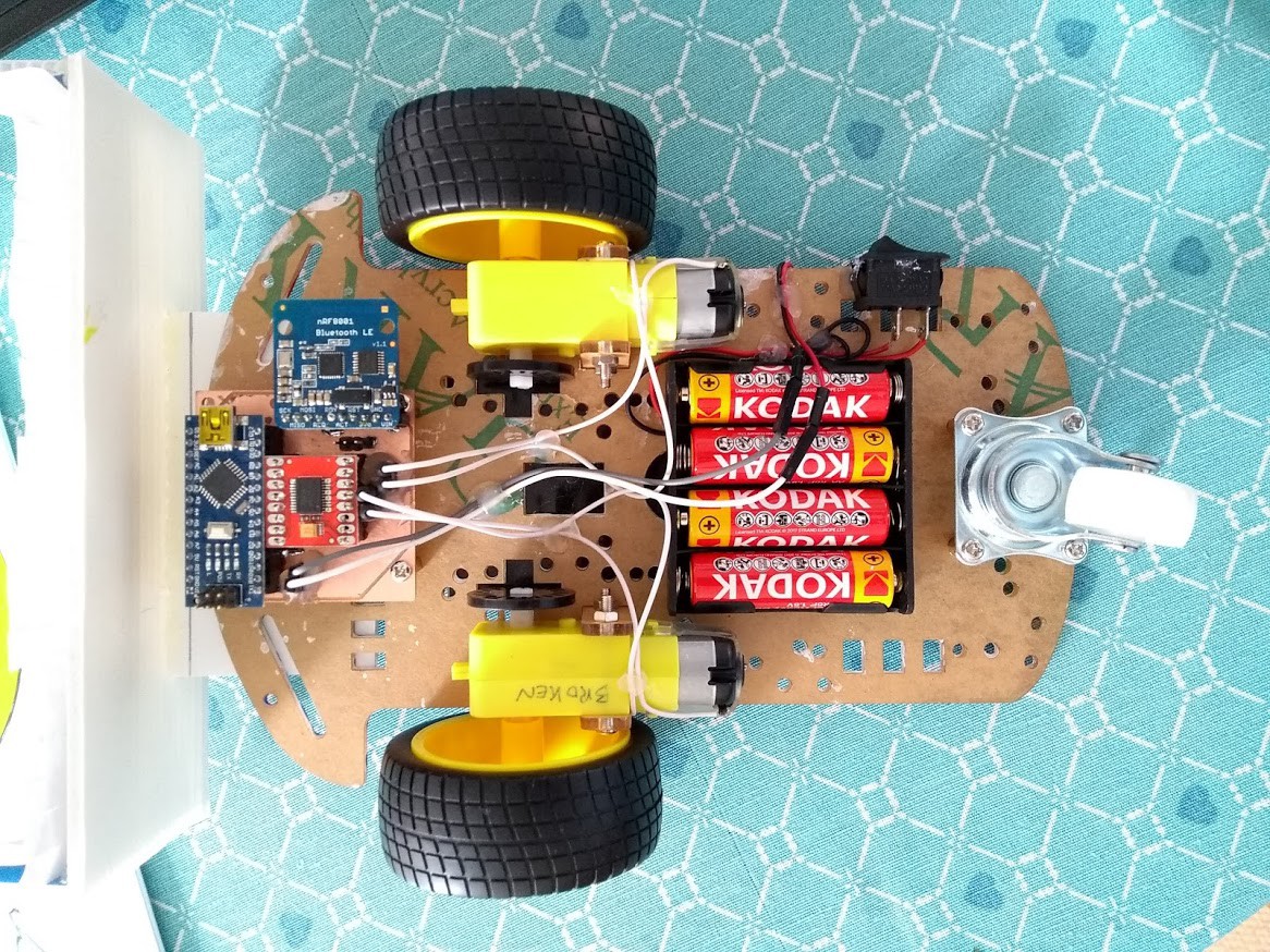
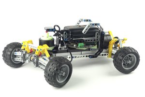
- Build a more sturdy prototype.
- Add a Raspberry Pi handling the bluetooth communications and providing a video feed for FPV.
- (potentially: use OpenCV to implement some basic autonomous driving)
 Cassio Batista
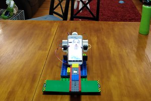
 Artur Majtczak
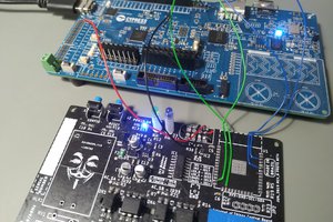
 Pedro Minatel