 Leon
LeonThe cart has one switch and one push button. The switch is usually in the normal position and only should be changed to the write position when the cart is programmed.
The push button is used to restart the computer to menu without having to turn off with the porwer switch. Only in the Atari 400/800 the button is unreachable.
To program this cart you execute FW32.XEX from atari dos but before the cart contents and the menu must be prepared. FW32 reads 32 files 32K each named slot0.rom to slot31.rom.
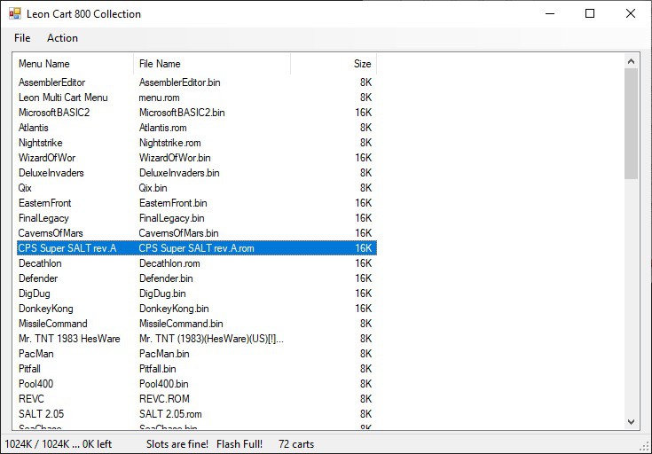
These files are prepared with the special windows software that allows you to add and arrange the files as they are written in the flash and appear in the menu. Slot0.rom also always contain the cart menu program that is the boot cart the first time the computer is turned on.
The program is called LeonCart800Collection.exe. You build the cart list using drag & drop of the cart files you wish to add. There are some restrictions in that the files should be divided in 32 slots of 32K so maybe you'll need sometimes to rearrange the list for this. Then from menu Action->Create Atr you create an .atr file and also the 32 slot rom files in the directory with name tempatrdir.
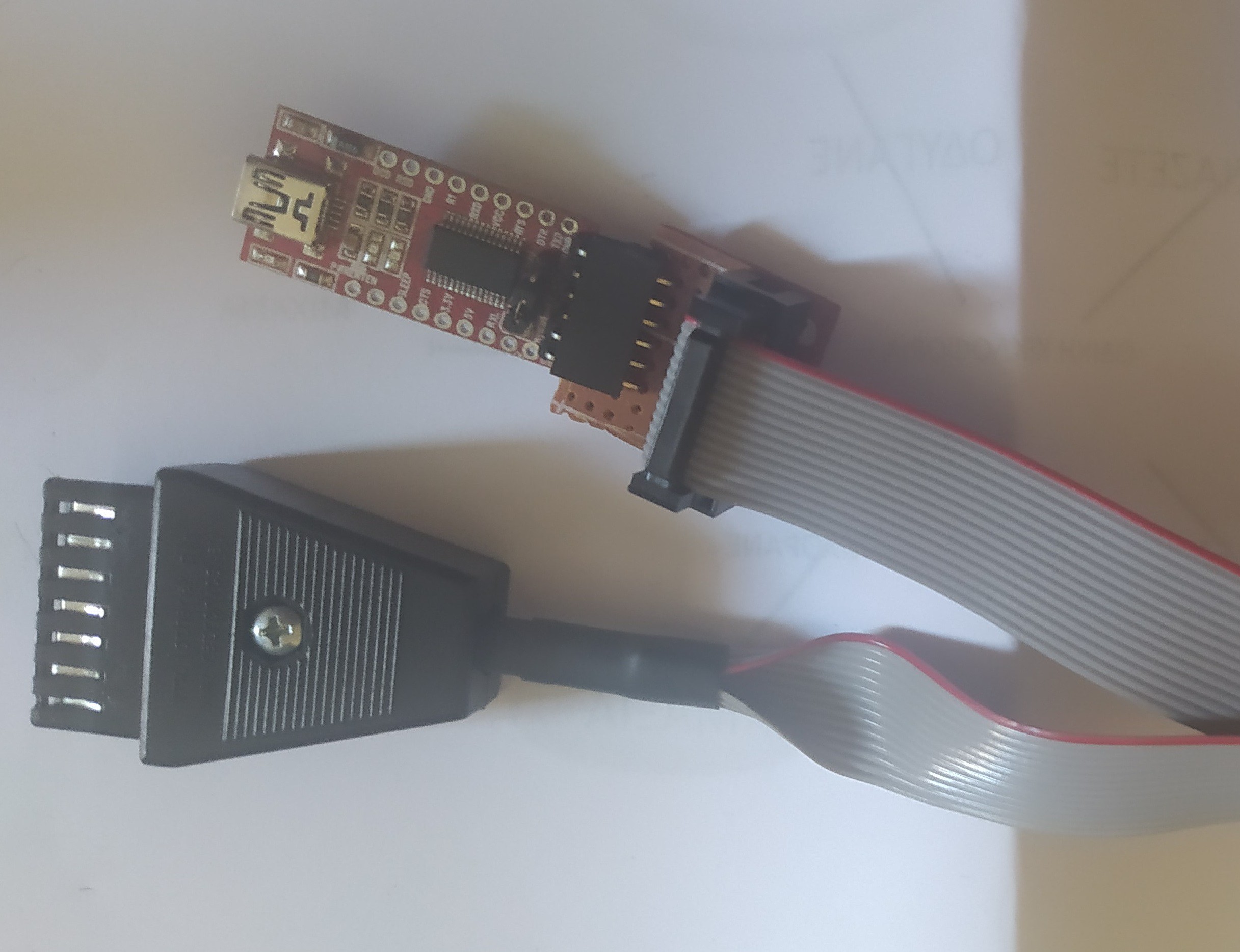
To program the cart I use a serial cable and AspeQt utility to mount the .atr file or the directory "tempatrdir" to atari. The flash of course should be empty or should have been erased. When the computer boots it enters dos menu and then using menu option L, I execute the program FW32.XEX that reads data from the serial connection to pc and does the programming. It takes several minutes.
Be sure you have a reliable connection between atari and pc. Don't interrupt the flashing procedure, some times the program makes a pause and continues after several seconds.
The cart can be erased while in the atari cart slot by pressing the SELECT key while powering on, and follow instructions or by program FE.XEX.
Hardware design and software released under the Creative Commons License BY-NC-SA


 Voja Antonic
 Angel Cabello
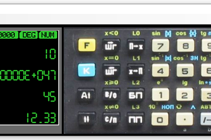
 ptrav
ptrav
 grossofabian
Excellent project! I am definately going to build a couple of these, it is perfect for my needs. The current silicon shortage almost requires an updated PCB design to use SMD components, the 14DIL TTL chips are on 52 week lead time everywhere. I am hoping it is ok for me to go ahead and do that new PCB from your original?