 danjovic
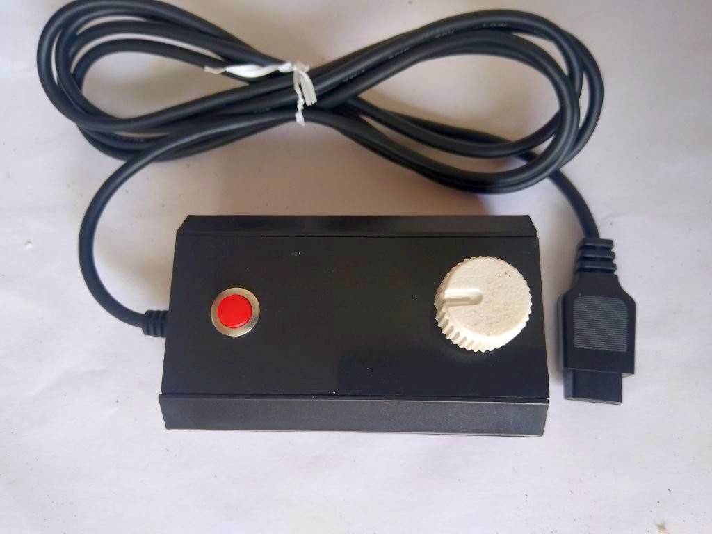
This project was designed to be a minimalist, easy to replicate, cheap Paddle controller for MSX computers.
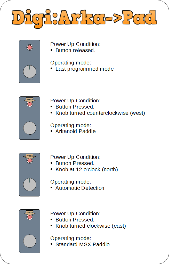
It provides two operating modes: Vaus Arkanoid Paddle and Standard MSX paddle. The operating mode is programmable and is persistent, which means that the default behavior is the last mode programmed.
There is also a third (pseudo) operating mode that performs automatic selection of operating mode based on the signals sensed from joystick port
Arkanoid Mode
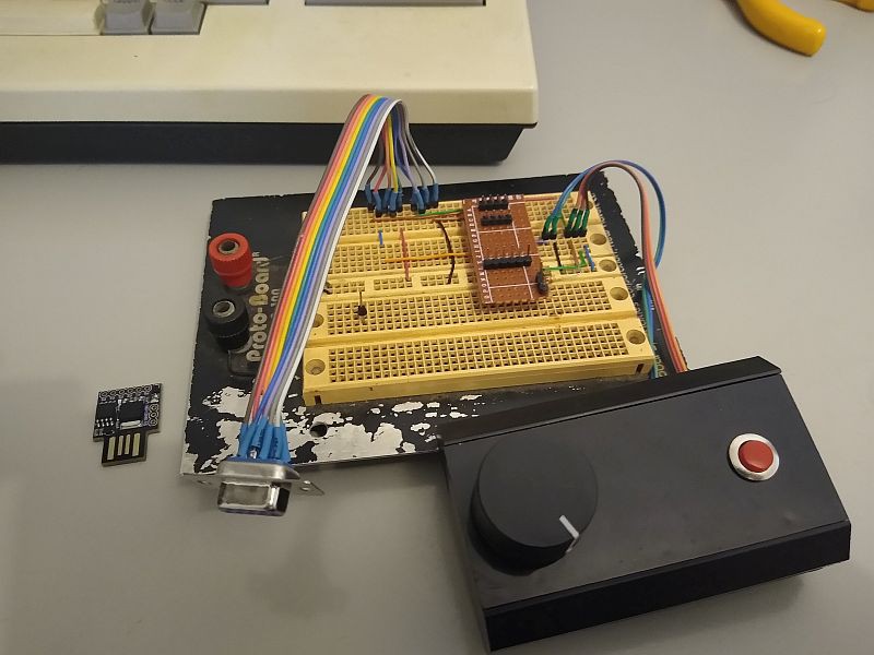
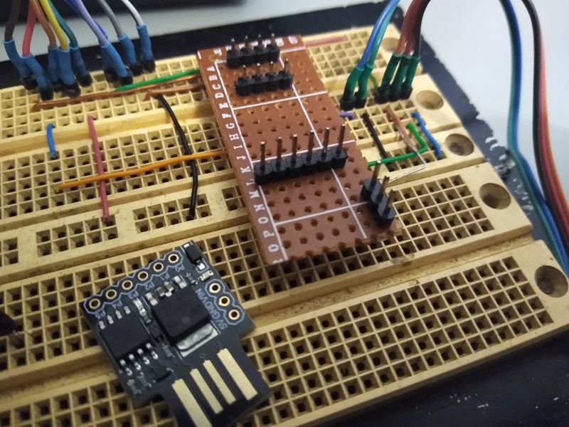
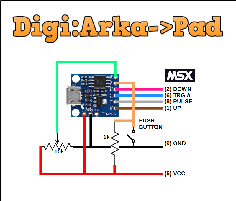
The Arkanoid mode is a tore down version of #SMSX paddle ported to the Digispark .
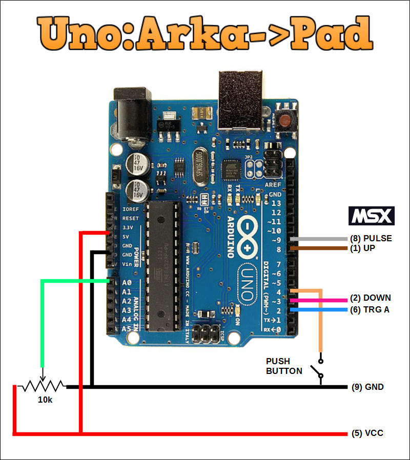
The communication with the MSX computer follows the protocol used in Taito Arkanoid paddle (Vaus) device.
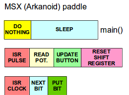
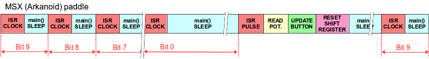
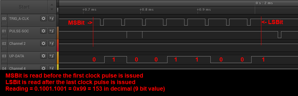
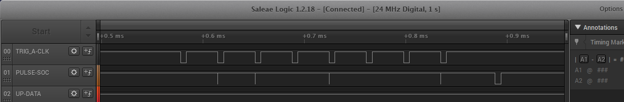
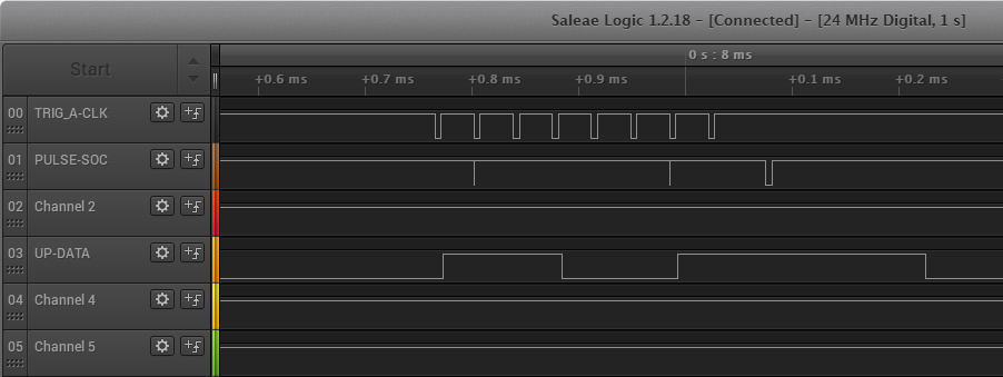
Each data bit is sampled then a brief low going clock pulse is generated by the MSX on pin 6 to shif out the next bit (data changes on risign edge). After the 9th bit is read another short going pulse is generated this time on pin 8. The rising edge of such pulse starts an ADC conversion. After the conversion is complete the most significant bit gets ready at pin 1 and the remaining bits are stored in a variable to be shifted later by pulses coming from pin 6. Button is sampled right after the conversion and pin 2 is updated accordingly.
Code is implemented using a couple of interrupts, one on pin 6 (clock shift) and another at pin 8 (start new sample). Main loop does nothing else than put CPU to sleep.
 Potentiometer position is read using the ADC and the 10 bit value is mapped to the defined limits.
#define MINVAL 110
#define MAXVAL 390
The value is read from MSX as a 9 bit value and the center value of such range is close to 256.
Standard Paddle Mode
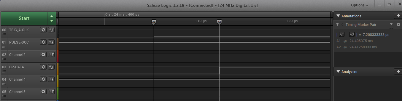
This mode uses only one interrupt, attached to the PULSE signal at pin 8. A positive going edge on this pin causes the CPU to wake and generate a 50us negative going pulse after a timing interval from 12us to 3.06ms in 256 steps (of 12us) according to the position of the potentiometer.
This behavior is slightly different from the discrete component based paddles (a monostable) and was adopted to avoid to deal with interrupt latency, as the discrete timers can change its output within nanoseconds from trigger pulse while the microcontroller (with standard C ISR handling code) takes some a few microseconds to answer the interrupt and change the state of the output.
Nevertheless teh 50us negative going pulse is more than enough for the Z80 to detect the end of the timing cycle.
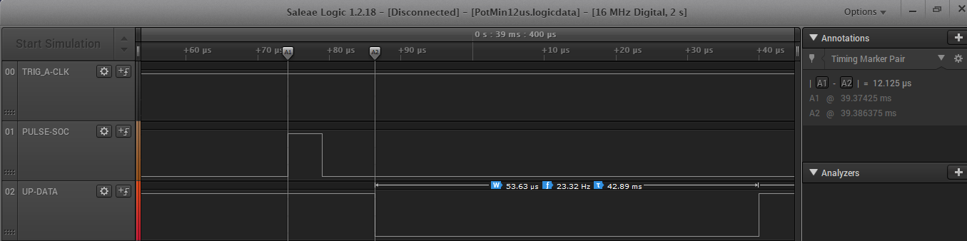

Timing for Potentiometer at maximum: 3058us
Automatic Mode
The selection of operating mode is done by analyzing the behavior of the Clock (pin 6) and Pulse (pin 8).
When executing Arkanoid game the MSX sends clock pulses on pin 6 during normal readings and issue a pulse on pin 8 to start a new conversion (potentiometer sampling). On the other While reading Standard Paddles the MSX only issues pulses on pin 8.
The detection routine counts both Clock and Pulse pin changes until it has detected
10 pin changes on Puse pin.
The DigitalRead( ) function is rather slow to detect all the changes and as a result the 10 pin changes detected on pin 8 will will not be equivalent to 5 full sampling cycles. For the same reason the counting of the Clock pin state changes will be far below the expected (16 changes per sampling).
The experiments performed showed that it is safe to assume that if at least one state change has been detected on the Clock line then the operating mode selected should be Arkanoid Paddle. If no State change was detected then the operating mode is Standard Paddle.
Notice that the Arkanoid game uses an heuristic to select to detect the type of joystick connected. When the game runs for the first time the title screen asks for pressing Fire Button. If the game detects the DOWN directional pressed (pin 2) then it assumes that there is a Vaus controller connected, and only then starts to issue Pulse and Clock signals.
That is the...
Read more »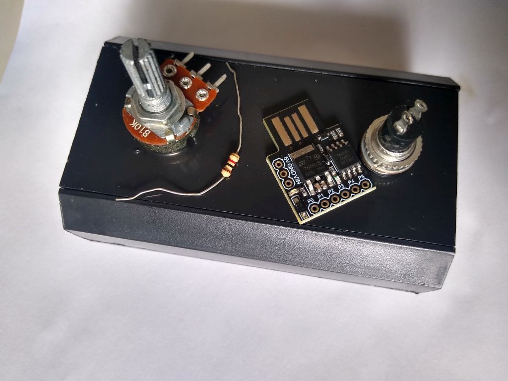
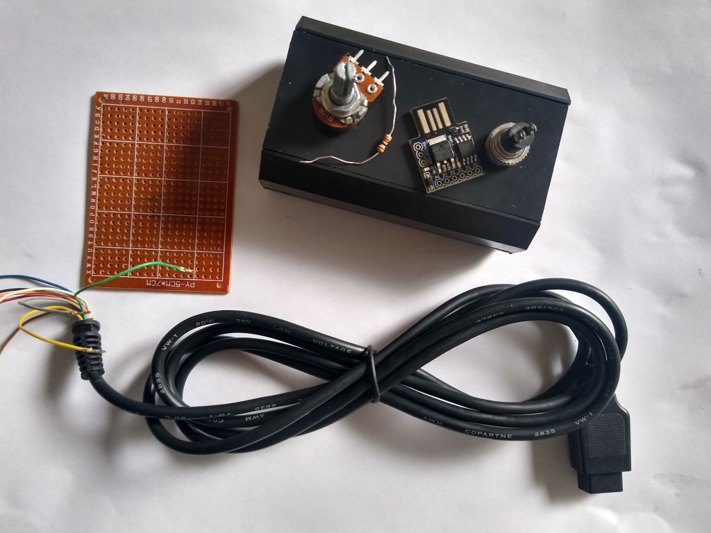
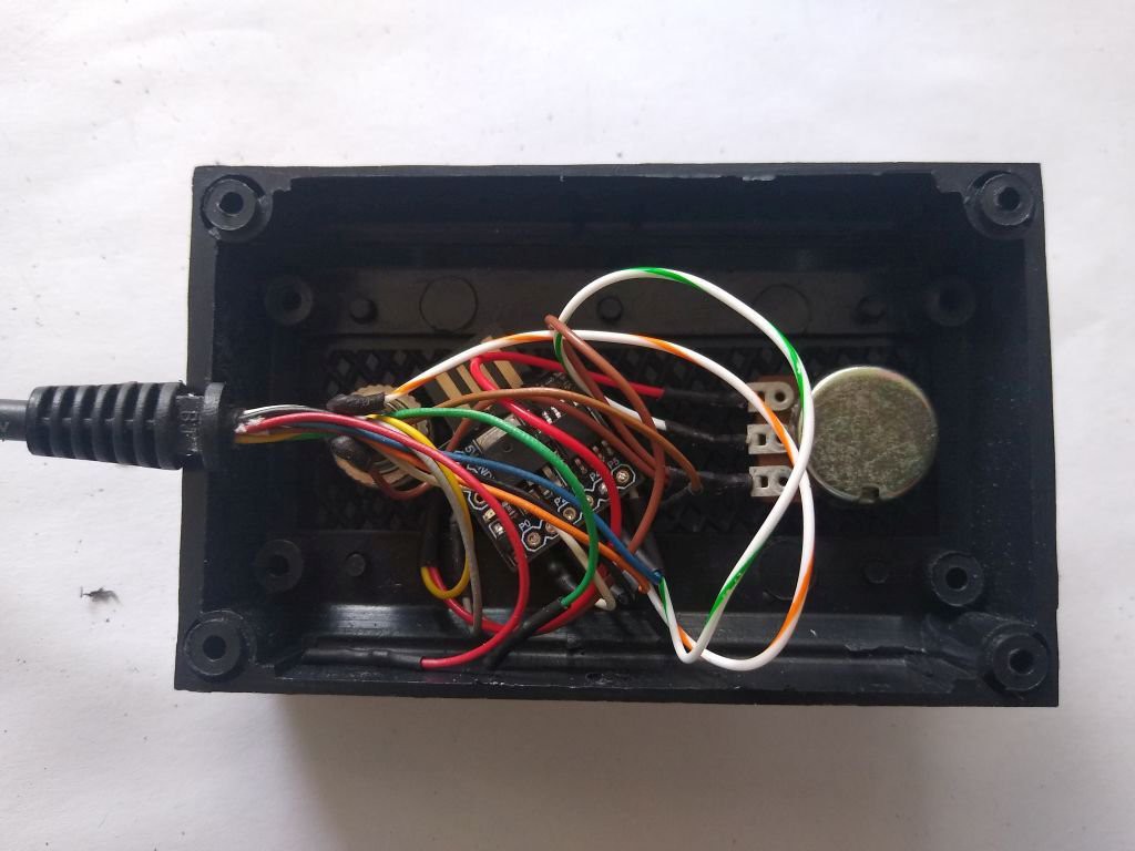
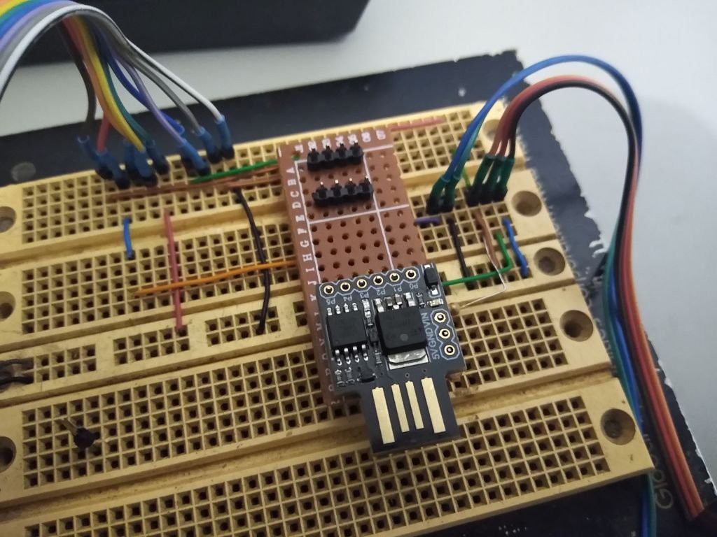
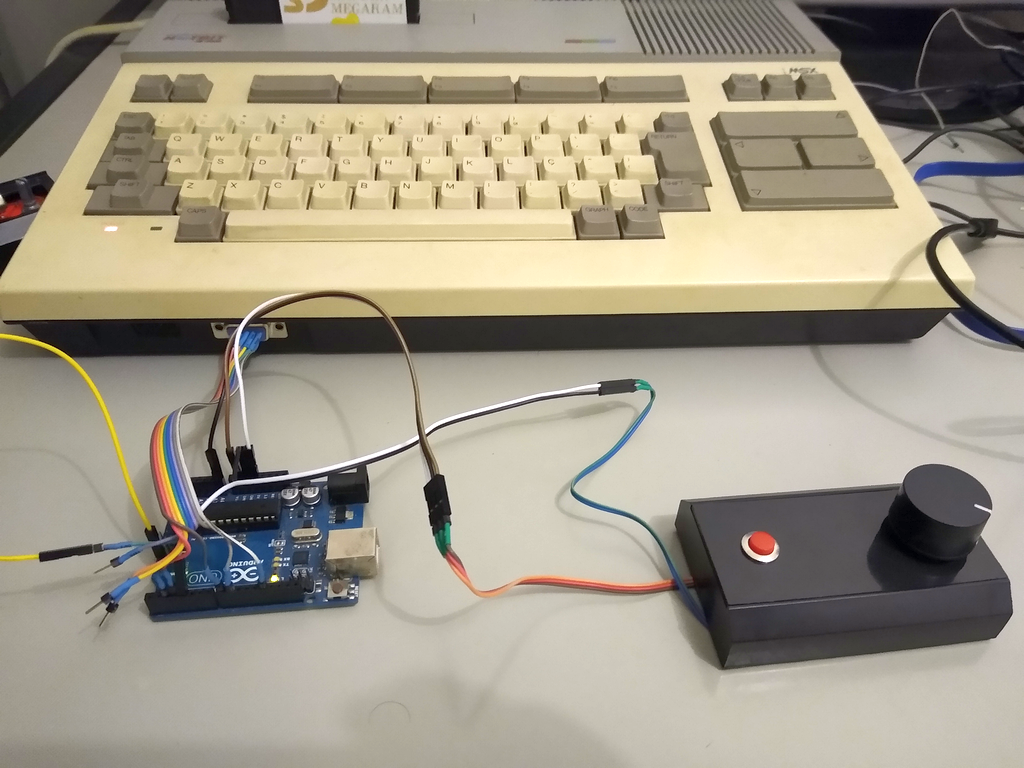
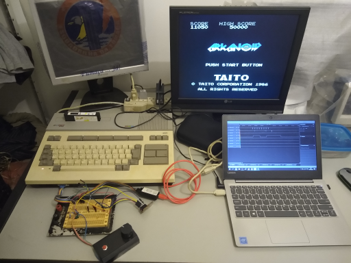
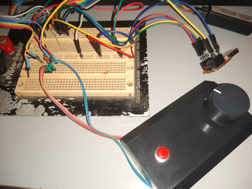
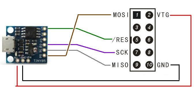
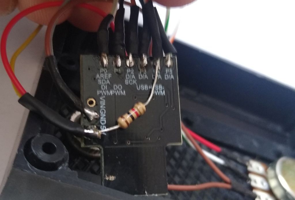 Everything wired
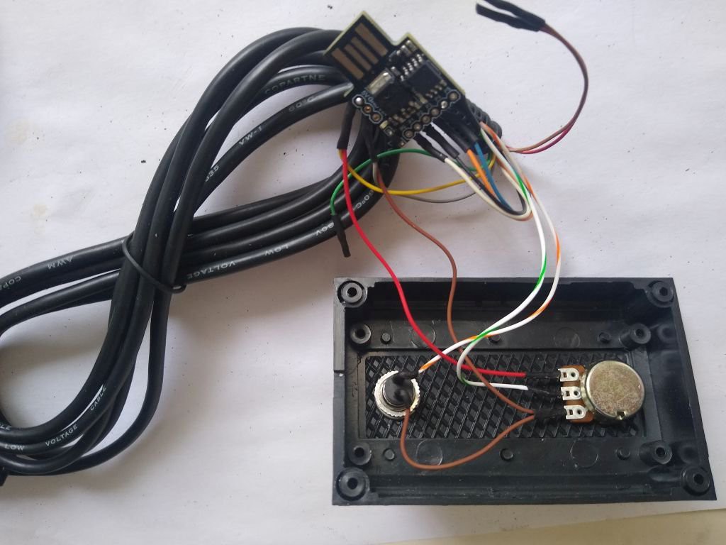


 Advice notice:

 Estudio Roble
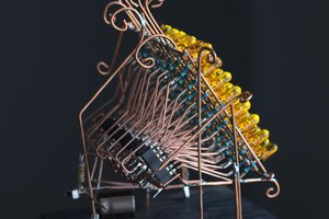
 Tauno Erik
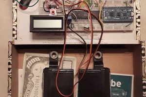
 xBeau
xBeau
 Abhishek Tiwari
Would this work in a bare ATtiny85?