In order to do some more useful experiments I finally designed a breakout board with PMOD connectors. Both PMODs on the sides are standard ones with 3.3V or 5V (selectable by a jumper). The header on the bottom is a double PMOD in the ULX3S style with 40 pins in total, which is a very clever and nice idea. Thanks to the Radiona folks!
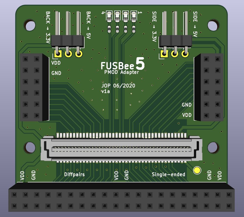 For ease of use and accessibility the headers (especially left and right) should be 90° angled (but the silkscreen for the straight ones is less crowded so I used it here). On the top are 4 additional LEDs for status indications. All signal traces are routed over a solid gnd plane, but without any length matching and impedance consideration (on 2 layers...yeah...).
I thought, the 2x40 pin Bergstak connector has an equal footprint for plug and receptacle and was nearly right. The only little detail is, that the two positioning pins on the bottom are of different diameter and if you would read the drawing very careful, you could recognise the need for a 180° rotation. Or just get the drill out and fix it...preferably before you soldered both connectors to the pcbs and try to mate them! ;)
With a specification of 100 mating cycles these were one of the better 0.8mm pitch connectors I found and they are available in many pin counts, heights and even a lower cost version. → Not bad at all :)
The suggested footprint in the datasheet can be used for handsoldering.
Current status of the FUSBee5 board:
- Hyperram is now fully connected (all series resistors are soldered in), but still needs testing → HDL action needed.
- Placement of the 4x0402 resistor packs should be reconsidered, as it is barely doable for hand assembly.
- It might be advantageous to replace both fixed frequency CMOS oscillators by a Silabs configurable PLL chip.
- The 3.3V buck regulator is quieter, as both ram chips are now drawing some idle current and the 1.8V are sourced from the 3.3V via an LDO. The 1.1V rail is still a bit noisy when the FPGA is not really doing much. → Load step response still on the list to be tested, additional Cs needed?
- The FT600 does not allow to configure the FPGA and only the JTAG option with an external adapter is currently usable. A little µC (as the LUNA project has) would be nice, but also requires some USB2.0 mux action to steal the Micro-USB 2.0 lines temporarily. → Not the prettiest solution and space-wise complicated.
- I selected M2.5 spacers to mount the FUSBee5 on any main board (MiCE47 had these huge M3 things...), but it seems quite hard to "cheap and easy" buy these things...why?!
Short term plans:
- Verify and benchmark the hyperram chips to finish the board bring up.
- Release the schematic/pcb design files with bugfixes/errata list.
- Compare the FT600 software options (FTDI vs libusb).
Discussions
Become a Hackaday.io Member
Create an account to leave a comment. Already have an account? Log In.