 Matthew James Bellafaire
The goal of this project isn't to completely automate everything nor provide a beautiful interface. The idea here is that the program is easy-enough to use without sacraficing the flexibility that circuiTikZ offers to the end user. Currently the majority of the functionality is in the project and I think its fairly intuitive to use but I also made it so that's not really a good metric. Here's a quick guide on how to use the program to create a simple transistor circuit in CircuitTikZ.
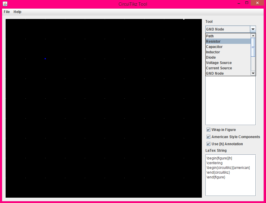
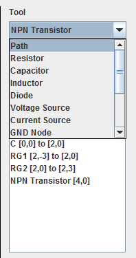
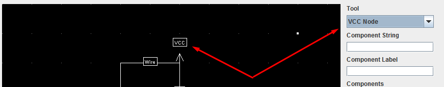
The main program window looks like this, it's fairly basic but we are able to select a tool from the drop down menu. Most simple "Path Tools" (basically anything that can be intepreted as a wire) are supported here. We can select from them and simply drag the mouse in the circuit grid to the left to place them as a path component.
So starting with a voltage source we select the voltage source from the tools dropdown and drag the mouse with left click held in the circuit window, this draws a wire which will be a voltage source in final compilation.
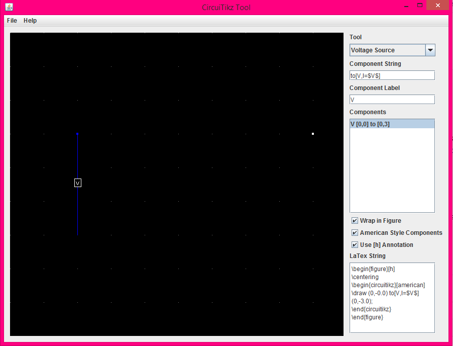
After placing the voltage source we select it in the "Components window" this is where we can select from all components currently placed (can also select the component and hit "delete" to delete them). Clicking on a component in the component window will result in the component's string and the components label field being updated. The "Component String" is what will ultimately end up in the latex code, the "Component Label" only changes the label that is displayed in the circuit window and the components list. This allows the user to organize things somewhat in a way that suits them.
Each component has its own default "template" which is just a little bit of code to use as a starting point in the case of the voltage source we start with "to[V,I=$V$]" which will just display the voltage source with a label "V" in the final latex schematic. We can change this for the purposes of our CE amplifier by modifying the text in the label to V_i (V sub i). Changing the component label makes it easier to keep track of components in the "components" list box.

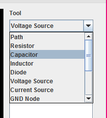
Next we're going to need an input capacitor, for this we go to the "Tools" dropdown and select capacitor, and once again drag the mouse to place our capacitor path.
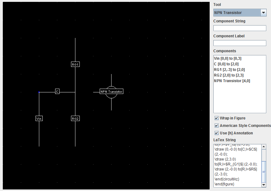
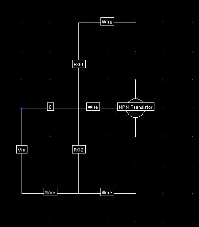
We also add some biasing resistors in exactly the same way until we get to this point
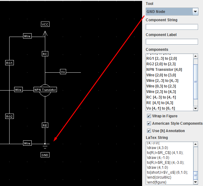
we can select the "NPN Transistor" from the dropdown and place that with a single click or holding left click to see a preview of the placement. All the transistors currently are only displayed using this 3-terminal icon, so they can only really be identified by their component label.
For simple wire's we use the "Path" tool, this just creates a simple connection between two nodes.
In exactly the same "click and drag" fashion as before we can place our wires on the circuit window
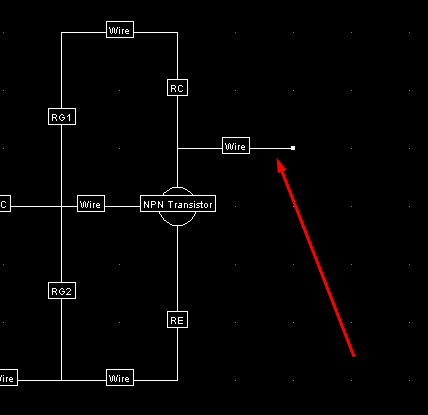
Few more resistors, and a wire going out of the circuit. At the moment the program doesn't support nodes that can be named (Comming soon) so we're just going to label the wire directly.
we can label the wire by adding a l= parameter to the "Component String" field after selecting the wire in the components list.
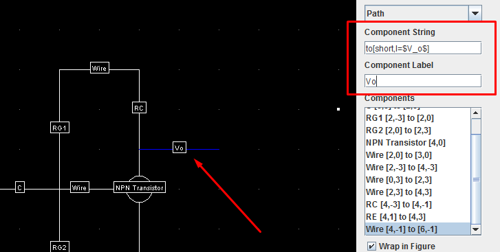
Changing the label also changes the display in the circuit window.
Now we just need to add our nodes for VCC and GND, which are both available as placeable components in the tools dropdown
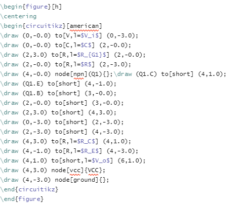
Now in the bottom right we have our "LaTeX String" output which gives us our figure to be pasted into the latex document. In order to have the circuit display make sure that your document has \usepackage{circuitikz} somewhere otherwise nothing's going to work right. If we copy and paste the entire output into our LaTeX document we can see that there's a lot that goes into a very simple circuit (Although this could be cleaned up quite a bit by hand if you wanted to do so)
And finally hitting compile will...
Read more »
 Rudraksha Vegad
 jaromir.sukuba
 mircemk
 Adam Redfern
LaTex is a type of software used to create professional-looking documents with text and images. LaTex is often used in engineering projects, but it can also be used to make posters, presentations, or any other types of documents. It is often challenging to use LaTex because it is not a user-friendly program. This program will help you create circuits faster by using pre-made shapes that you can drag and drop into your document. This program will also allow you to save your work on the computer's hard drive so that you don't have to constantly be saving your work. I want to know why video games can have stronger influence because I have learn Better Visual and Spatial Skills recently.