Specifications and Constraints
Pressure sensing accuracy must be within +-1cm H2O.
Volume flow rate accuracy must be within +- 25ml/min.
The cyclic rate of the tidal volume must be controllable to within +- 0.5 bpm. The rate must be configurable between 10 – 30 bpm.
Pressure sensor
Critical components of ventilators are the pressure sensors. Good pressure sensors are needed to keep the pressure within the bounds stipulated in the specification provided.
Table 1: Comparison of applicable sensors
|
| BMP280 | BMP388 | XGZP6847 |
Precision | 0.00163 cm H2O | 0.00163 cm H2O | Determined by MCU ADC Resolution |
Accuracy | 1.019 cm H2O | 0.51 cm H2O | 1.019 cm H2O |
Sampling Rate | 157 Hz | 200 Hz | Determined by MCU Clock Speed |
Cost | R60 | R60 | R180 |
The XGZP6847 is a differential pressure sensor which would compensate for external pressure fluctuations. An important consideration if the device is to be used in Cape Town (101KPa) as well as in Pretoria (86KPa). Another important note about the above devices is that the actual pressure sensor on the breakout board of the BMP280 and BMP388 costs about the same.
Availability of sensors will be the deciding factor between the XGZP6847 and the BMP280 as their performance meets the specifications.
Venturi - flow sensor
Air flow rate sensors are generally in excess of a few thousand rand. Alternatives such as a venturi could be used to keep costs low. With the use of a 3D printed venturi nozzle, repeatable characteristics will potentially be achievable. Tuning the relationship between pressure and flow can be done with a well documented flow meter.

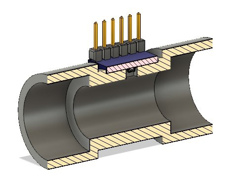
The upstream flow sensor design is in the figure to the left. It just measures the static pressure of the air at some upstream location to the venturi.
The Sensor is a bmp280 module. Future designs will use a custom pcb for cost reduction.

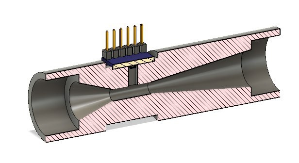
The venturi is pictured in the image on the left. The sharp taper, 20 degrees, is the inlet and the 7 degree taper is the outlet.
The venturi has not be tested. The lock-down in SA is limiting access to proper equipment.
Hot air anemometer - flow sensor
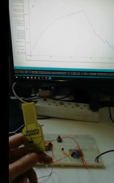
A hot air anemometer measures the rate of heat loss from an element by measuring the elements resistance in some way. The prototype shows promising results but actual performance of the device has not been measured.
Blowing on the element lightly produces a smooth waveform. Hopefully in the coming week it will be tested and proper specs will be given - accuracy/repeatability between sensors.
Flow/pressure control
Altering the duty cycle of solenoids rapidly switching could potentially be a cheap method of producing pressure/flow wave forms from a higher pressure buffer. This method is being investigated and progress will be uploaded.
Using servos mounted on ball valves is another option for flow/pressure control.
These two methods can both work potentially but, again, availability will be the deciding factor. Ideally both methods should be developed to a usable device.
UV filter for killing pathogens (not viable - more expensive that HEPA filters)
Although the wavelength of these UV LED's are not ideal. They are still UVC and thus can potentially be used to clean the ventilator exhaust air. The benefits of this method over filters is the reduction of consumables and the reliance on suppliers.
Critical factors for sterilization using UVC include LED irradiance, exposure time and fluid velocity.
The initial idea for this is a cylinder with a slanted input to induce an air vortex inside so that the same air does multiple passes over the UV LED's. This concept will be investigated at a later stage.
Solvent based air filter
The air leaving the patient can be bubbled through a liquid using a fish tank aerator. The liquid will be a strong solvent that breaks down the viruses outer shell. The viability of this has not been investigated.
Water purification fluorescent lights for filtering air
Fluorescent lights for water purification are a magnitude cheaper per watt in comparison to UVC LED's. They are not the ideal wavelength but could potentially work.
Design concept 1

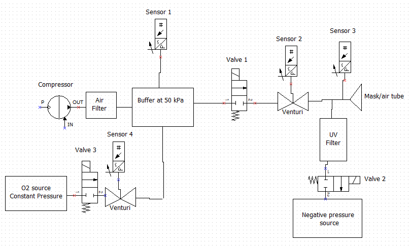
Using mosfets the compressor can be turned on and off using the buffer pressure sensor as feedback. The buffer will be kept at 50 kPa. This is necessary for a more stable final output.
Valve 1 is then used to shape the pressure curve at the mask/tube using the venturi and sensor 3 for feedback.
The negative/low pressure source drains the patient using valve 2 and sensor 3 for feedback.
 Simon Harvey