Features
It's a hybrid of a finger brake and a wiping bender.
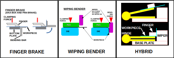
It uses holes for alignment rather than working off the edges of the sheet metal.
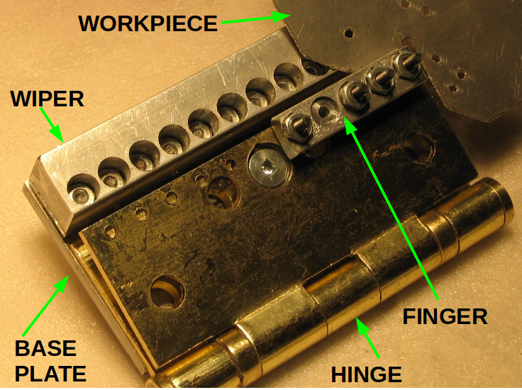
 Machine screws sandwich the upper hinge, the workpiece, and the finger. The position of the bend is determined by the position of the holes in the workpiece.
It uses a ball bearing commercial door hinge, a bit of aluminum plate, some bar stock, and quite a few machine screws and nuts.
The ball bearing commercial door hinge has very little slop. The fingers are made from 1/4" x 1/2" rectangular aluminum bar. The corners are round with a radius of around 1/32" (0.8 mm). This produces a reasonable bending radius on the workpiece materials that have been tried so far.It makes good use of a PCB mill or desktop milling machine to mark and/or drill holes.
Absent a mill, you could print designs on paper and transfer them to metal.
The local office supply store can print on quite large pieces of paper. This link covers the issues. I haven't tried it yet for a project with this bender.Applications
Mechanisms like gear boxes where precision is necessary.
Things you can't build any other way.
If this can be automated to remove the drudge work, sheet metal is excellent material for all kinds of projects.
Disorganized thoughts
Rivets, holes, machine screws, wear
The original thought was to use 1/8" drill bits and use 1/8" pop rivets for fastening. The bender would use 1/8" dia. machine screws. Hah!
The pop rivets want holes larger than 1/8". A #30 drill is suggested.
#5 machine screws have a nominal diameter of 1/8" (ie. 0.125"). The measured diameter on the outside of the threads was closer to 0.120" for one box. Anyway I could feel the machine screw wiggling in a hole drilled by a 1/8" bit.
Interference fit
Using a #31 drill, the #5-40 machine screws tap their way through aluminum. Presumably, this tight fit would result in greater accuracy. This also works for the fingers.
Wear
The holes in the fingers seem to wear rather quickly. The solution is to counterbore holes for the nuts. The nuts, being held in place, provide the accuracy. terminology
Screw position accuracy
The holes in the steel hinges are drilled with a 1/8" drill bit. However, the holes in the hinge are countersunk. The slope of that plus the slope of the thread angle of the nuts force the machine screws into the correct position in the holes.
A couple of things you can't do with a finger brake
1 - Because the fingers are mounted on some kind of structure, that sets the maximum depth of box you can bend on a conventional finger brake. link
2 - You can't work off the end of a finger brake.
3 - Because the bed and the apron run the length of the finger brake, it's hard to offset bends.
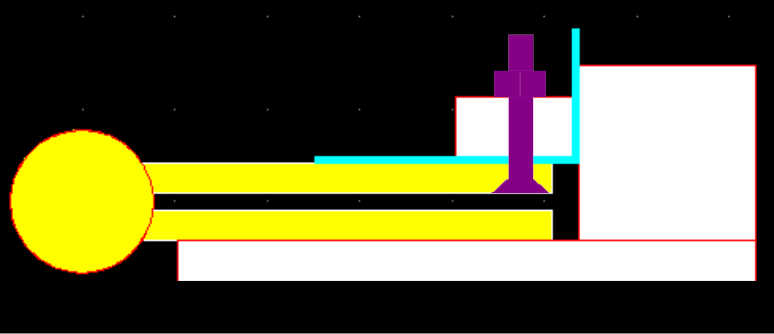
The picture above shows a tab about to be bent. Note that most of the workpiece overhangs the bender on the right.

In the picture above the bend of the tab is offset by one material thickness (MT) behind the bend of the side behind which it will end up after the next bend.
Spring back
When you're bending sheet metal, you usually have to over bend a bit so the part will spring back to where you actually want it to be. link
Finger - front profile
The working face of the finger is profiled for two reasons. The curve of the blending edge is preserved. Above that the edge is recessed to avoid interference when an adjacent tab gets sandwiched between the finger and the workpiece. The front of the finger is also raked back to allow for some overbending.
Bending radius
So far, three thicknesses of aluminum have been tried: 20 ga. (0.81 mm), 28 ga. (0.32 mm), and 32 ga. (0.2 mm). All three have bent tightly around the working corner of the finger. It's curved with an approximate radius of 0.8 mm. All the bends came within a degree of a right angle.
A test piece of 40 mm wide, 24 ga. (0.64 mm) stainless...

 Kert
Kert
 [zit] Olivier Gade
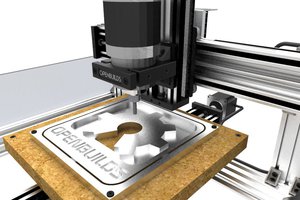
 charliex
 enrique
Interesting concept. I'd love to see a large version.