 Andrew Clapp
Introduction
I'd like to share how I use 7 segment displays and STM8 boards to monitor/display numbers of any kind. This started out as a project for work, but quickly escalated to something a little more interesting, and challenging, and maybe even useful. So here's the story, and I'll try to keep it short. And I'll even try to put the good details up front so you don't have to wait.
This project rests on the shoulders of others and it's not at all 100% my own creative doing, but a lot of this may bridge the gap for some of you out there who want to do this type of thing, so I'm sharing. I'm pretty jazzed about this and I hope you are too. Some preliminary thanks to Thomas for sharing the bulk of the information I've relied upon and his super awesome willingness to prod me in the right direction. Thomas also has a github site for stm8ef and other projects you can find here on Github. The site Bare Metal Programming and a great blog get some serious read time credit to lujji! A great many good vibes to Robin for this page https://maker.pro/custom/tutorial/using-gpio-on-stm8-microcontrollers and all that good info. A huge thanks to the Sduino Project and all the detailed info about the blue pill board. I welcome feedback, comments, and corrections regarding this page.
Hardware
The STM8 comes in a variety of shapes and sizes, and Thomas has covered a huge swath of them in great detail and has provided a lot of more generalized details about the STM8 line and the devices that you can find out there. I'm intending to cover only just this one, because it's popular, inexpensive, easy to use, and what I have on hand at the moment that works for my development needs for the project I started out to finish. I'm accomplished the task a few different ways, but I am after a better way, always. I'm using the STM8S103F3P6 in a board that brings all the pins out to the edge so you can get at them, and you can install header pins and make it plug right into a protoboard. I grew up in the era of Radio Shack's popular books by Forest M Mimms III, which featured many circuits, using a breadboard or protoboard, and dip chips and transistors and other small component to build a large variety of applications and educational demonstrations. The protoboard is probably the easiest way to get this stuff built so you can play with it, adjust it, experiment with it and learn things while being productive.
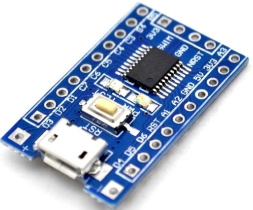
Hardware setup. Blue Pill STM8 board for under a buck. 4-digit seven segment display. Serial interface. USB "swim" programmer. Breadboard. a 10K to 25K pot and 8 limiting resistors for your LEDs (almost anything from 220R to 1K should do, as long as you've got a handful of them). And header pins, or just some bits of the right kind of wire if that's all you've got. The pins are cheap, buy a bunch. And a linux box (ubuntu worked well), and you might get a nice multi-port powered USB hub to make things easier on yourself.
Software
Rev 1: I used the Arduino IDE and the "sduino" bits that I found out on the web. This let me write in C and allows for reasonably readable and easy to write code, and a binary of about 5200 bytes. I'm sure I can do better, the things only got 8K, and I want room to move around in there...
Rev 2: ... So I try my hand and cobbling it together in SDCC from source (and librarie files borrowed from all over the place) on my linux box. I borrowed a little #define macro here, and a little idea about a smarter way to do the thing I was doing there, and a little speed increase by trying more direct GPIO over here, and pretty soon, I'm looking at a reasonable facsimile of a running hunk of code on the proto and it's more configurable, faster and only about 4500 bytes and change. Woot! I'm happy about how much room I've got to may play with log files for my application, but the code has to get bigger to make that happen too. So naturally, I start wondering if there's a better way. For me, putting something like this together resembles a combination of painting, using the colors I can find that work on the parts I have and go well together, and assembling a LEGO kit from the instructions, but not having all the exactly correct pieces, so I sometimes have to improvise.
Rev 3: Next up and in progress, Forth, in particular eForth (which stands for Embedded Forth). Check out Thomas's eForth github repo. So as of this writing my application of Forth to my particular hardware is not working 100% yet, but I'll get there. I'll amend that a bit, I was able to get forth to the point where I could program my board in Forth far enough to control each segment of each LED and read analog input data from the ADC. All of this was done via a serial link, which I first did not have so I built one to work with what I did have based on this serial to ttl circuit. However, as of yet, my forth chops are not good enough to accomplish the entire goal. All I knew is that my hardware was talking serial, and all the I/O pins were doing the things they were supposed to. I'm confident that I'm now close to the point where all the info crammed into this is going to start paying off. First non-refactored bulky eForth build for this board with my pin layout was about 5000 bytes, but I know it can be much smaller. I'm keeping track here for you, and so folks can experience what it is that makes good code, smaller and faster code, more efficient to run, and why we might want to chase after something like that.
An additional idea that popped up from my past is to eventually read the number you're displaying via serial and drop it into a cacti graph. This is one of the old standards for monitoring changing data points (network traffic, machine memory and load and disk space, etc) on large networks of computers. A simple shell or perl script is run periodically that "polls" the device and gets a number, and then formats it nicely for input into the monitoring system. You could also use nagios if you got that motivated. Petty soon you can watch changing graphs of your devices outputs and even alert yourself via email if they do certain things.
Stumbling Blocks
Along the way, I've run into a number of things I did not know, and another number I did not expect. I was very surprised to find that my SWIM connector apparently does not connect it's ground to anything useful on the board, like say, the Vss (pin 7) ground connection for the chip. There is still a bit of mystery for this and I'm not 100% sure what's going on. My work-around was to run a physical wire from my USB programmer's swim ground lead to pin 7 on the the chip. This allows my USB programmer stick to power my STM8 while I work on it, program it, change things and iterate. The board/chip seem to be pretty durable so far, as I am the king of breaking things, and it's still working after I've done a number of questionable things like put too much voltage on inputs that I was sure would fry the circuit in some way. So, don't panic, it's just a $1 if you break it. I've also started building a few of the smaller types that use the STM8S003 chip and a little green breakout board with no frills (no 3.3V regulator, no caps, no reset button, no swim header). My work project uses that chip, so I'll have to verify that my code runs there too.
There are two pins on this STM8 that can't do what other pins do, and this is good to know in advance when planning your pin layout. The pin 11-12 (PB5-PB4) pins are "true open-drain". Most pins are configurable, some can do many different things, but in particular, GPIO (general purpose I/O) pins can be inputs or outputs, and they can be set to act as one of multiple types of output in particular. The two important ones are push-pull and open drain. A push pull output can drive a 1 (high digital signal) and a 0 (low digital signal), or in other words they can supply current (source) or accept current (sink) from the surrounding circuit. An open-drain will not be able to drive a solid digital 1 by itself, but it can ground and unground a circuit well. That is it will ground a circuti by suppling a digital 0 (ground/drain) or be ungrounded (open). There are also current limitations, and the source/sink maximums for a given chip are in the datasheet. In the case of driving a 7 segment LED display, you could have a common anode or common cathode configuration. The common anode is what I'm working with. I wire up a single gpio pin that can supply a digital 1 to the anode, and 8 (7 segments and the decimal point) wires to the various segments that can include "true open drain" pins like PB4 and PB5. As an additional note, you can use them to make a digital 1 with an external pull-up resistor.
The LED segments can exhibit a rather large variation in brightness within each unit, and we may want or need a more uniform look, so it's best if you can use a single resistor to current limit each LED. You could use a single resistor on the common anode, but the more segments you light, the more current you pull and Ohm's law gives you a higher voltage drop. If you're operating at 3.3V, and you have 8 led's pulling current, you may not even be able to light them up at all. Instead, use one resistor per LED. I have used 100 ohms up to 1K. I've only used about 4 types of 7 segment displays, but there is some variation in the current they pull and their brightness. I really enjoy the blue ones I ordered, and they appear brighter than the other green LEDs that I've tried, but they're more expensive too.
If you want to use eForth, you need to be able to talk to the chip. If you want to be able to talk to the chip while it's running so you can check log files or keep an eye on stuff in some way, you might want to free up the serial data communication pins (2 is Rx and 3 is Tx). These are used to let a serial console on your linux box connect to the serial I/O on the chip and let you have an actual interactive "shell" in Forth! This part is particularly exciting to me. :-)
Power is always an issue, so you might pick up some powerbricks or some of the inexpensive buck/boost technology available on ebay these days. I have tried several different ones, and I like most the ones that take a usb plug to provide 5V, and then are adjustable and can supply a wide range of output voltages that cover 3.3V for smaller projects like this, or 12V for running relays. There are even high voltage boards that can supply any where from a few hundred to over a thousand volts.
Some Code
I like writing in C because I'm familiar with it. C and perl are my go to languages for getting stuff done. C reads logically to me. The absence of strict formatting is definitely a win for my style of doing things. And now for some code to banter on about. Let's cover just a little bit about GPIO.
int pin = 3;
int value = 1;
pinMode(pin, OUTPUT);
digitalWrite(pin, value);
If you are programming in the Arduino IDE you are familiar with this and what it does. It sets the value of the output on pin 3 to high. Or you can say it puts a value of one in the output data register of the chip that results in this output. Down deeper, if you omit the pinMode line, your led may not light. Why? Control registers. These are what you need to learn more about if you stray from using an IDE lie this one that is doing some stuff for you behind the scenes. The pinMode statement sets the control register to configure that pin for output. It may also configure which type of output. Each IO pin on the STM8 belongs in a group called a port. Ports are cool and really useful and let you do things in parallel, say write 8 different bits to 8 different outputs at once. And by at once, that means faster than writing 8 bits to 8 outputs one at a time. You probably won't do much with this parallel stuff on the merely-20-pin STM8S103F3. You may find it useful when more pins of a given port are made available at the pins in chips with more pins. However, understanding how they work is essential!
GPIOD->CR1=0b00000001;
GPIOD->CR2=0b00000001;
GPIOD->DDR=0b00000001;
GPIOD->ODR=0b00000001;
This blob of code is a few things, and it's permissible in some environments but not in others (sdcc). We are doing things directly at the register level. The registers in play are CR1 and CR2 (control register 1 and 2), DDR (data direction reg.), and ODR (output direction reg.). Each one is 8 bits wide, and in this case we are dealing with port D, as indicated by GPIOD. When a bit in CR1 is set to 1, the pin 's internal pullup resistor is engaged, if 0, then it is left floating, CR1 sort of chooses push-pull or open-drain configuration. And there is a FET involved and it is interesting to say the least. This choice may depend on if you want it configured for input or output and how your circuit is built. CR2 will select the use (or lac) of interrupts on input pins, and speed on outputs. Again the internal FET and resistors. DDR is the direction in which data is flowing, in when set to 0 or out when set to 1. Finally ODR is the output data register.
As with anything good, there are more than one way to do things.
Example 1:

#define setBit(reg, bit) (reg = reg | (1 << bit))
setBit(GPIOA→DDR, 3); /* Set bit 3 on port A as output */

Example 2:

#define _SFR_(mem_addr)     (*(volatile uint8_t *)(0x5000 + (mem_addr)))
#define PD_ODR      _SFR_(0x0F)
#define PD_DDR      _SFR_(0x11)
#define PD_CR1      _SFR_(0x12)
PD_DDR |= (1 << LED_PIN); // configure PD4 as output
PD_CR1 |= (1 << LED_PIN); // push-pull mode
PD_ODR ^= (1 << LED_PIN);

Example 3:

MOV     PA_DDR,#0b00000100
MOV     PA_CR1,#0b00000100
The first and 2nd examples above uses a #define macro, or a handy way of doing substitutions in C. The third is done in assembler under sdcc.
The Long Story
And now, more on the background story... We needed to display some voltage and current on a device we make at work, but we were unable to get some of the parts overseas in the quantities and dependability that we require. So, I figured, this is going to come back to the US eventually, so let's make as much of it from parts we can get right here for now. And in the process, I wanted to brush up on my rusty tech. I stared programming on an Apple IIe's 6502, so I learned all I know about BASIC and Assembler from that. Turns out, the 6502 assembler I learned then has really gone far, but I'm no pro at assembly language, so YMMV. I mostly like to write in C, but let's just say I'm Forth-curious.
More recently, like as in the past 10 years, I've been using the teensy micro for a lot of projects. I have used the audio board, the touch screen display, the xbee wireless boards, 7 segment displays, relay control boards, and more. The teensy is made locally here in Portland so I also have attended Paul's workshops and I have nothing but good things to say about all that work being done.
I built a little protoboard project out of the inexpensive stm8 "blue pill" and 4 single digit 7 segment LED's that I pulled out of a microwave or a coffemaker, or toaster or some crazy thing that I had. I used to be the person that would never throw anything away until I had pulled all the bits and pieces out of it that I could identify and maybe use. Even some of the metal leftover brackets from ikea furniture, you know those wall-mounts for shelves that no one every uses, they get used in my projects, twice now. Handy little pieces of metal, those are!
The next demo was a blue pill again, but I actually got to use a full 4-digit mux'd 7-segment display. For the proto, I am just using a single analog input, with a 10-25K pot between the 0 and 3.3V rails to send a voltage to it off the wiper. The ADC reads out a number from 0 to 1023 (at 10 bits, that's what you get). The display is wired to 8 gpio pins for the numbers and decimal point, and another 4 for the digits. The displays I'm using are common anode, but you can do the needful to make them common cathode compatible. With Forth, I also wanted to have a serial console, so I could have logfiles to read and just being able to have an intelligent conversation with an 8-bit machine is kinda fun. So for the blue pill, you end up using almost, if not all of the pins depending on your approach. The whole project is inexpensive, and that's a win for experimenters and production-minded folks alike.
Way back when, I used to work at HP in Corvallis, OR, and there was a guy there who was all about forth, and he gave me a book by the same name, and a few others, starting forth, thinking forth, and I really dug it. I later used some of the know-how with Sunn's Openboot when I got to the part of my career at Sequent, but that's another long story. The beauty of the mixture of forth and microcontrollers is hard to miss. Forth is great at working in small spaces, with limited resources.