 Phil Malone
Overview
My ultimate goal for this project is to develop an open framework for adding low cost power systems to unpowered mobility devices used by children. I like brining "structure" to a range of existing solutions, so my plan was to choose a suitable mobility platform (in this case, the ubiquitous Hoverboard) and devise a strategy whereby tech-savvy hobbyists could add a power drive to just about any wheeled device.
Here is the current status: as a 5 min video Log.
I've teamed up with a Occupational Therapist who's function is to focus my goals and provide real-world challenges for me to base my solutions around.
I will develop and evolve requirements and interface spec's as I explore the world of assistive devices. I will document the project progress here, and publish code on Github.
Here's an easy way to absorb this project in nice chunks:
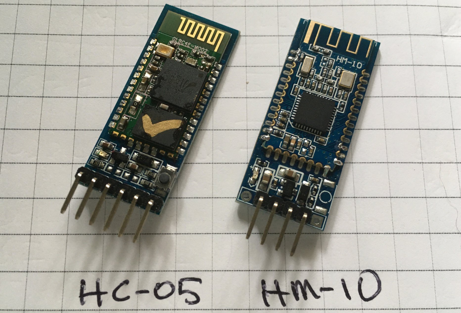
- Log #1 Hardware Research
- Log #2 Researching Firmware
- Log #3 Exploring Existing Firmware
- Log #4 Developing HUGS
- Log #5 Going Wireless (not)
- Log #6 Motion Control
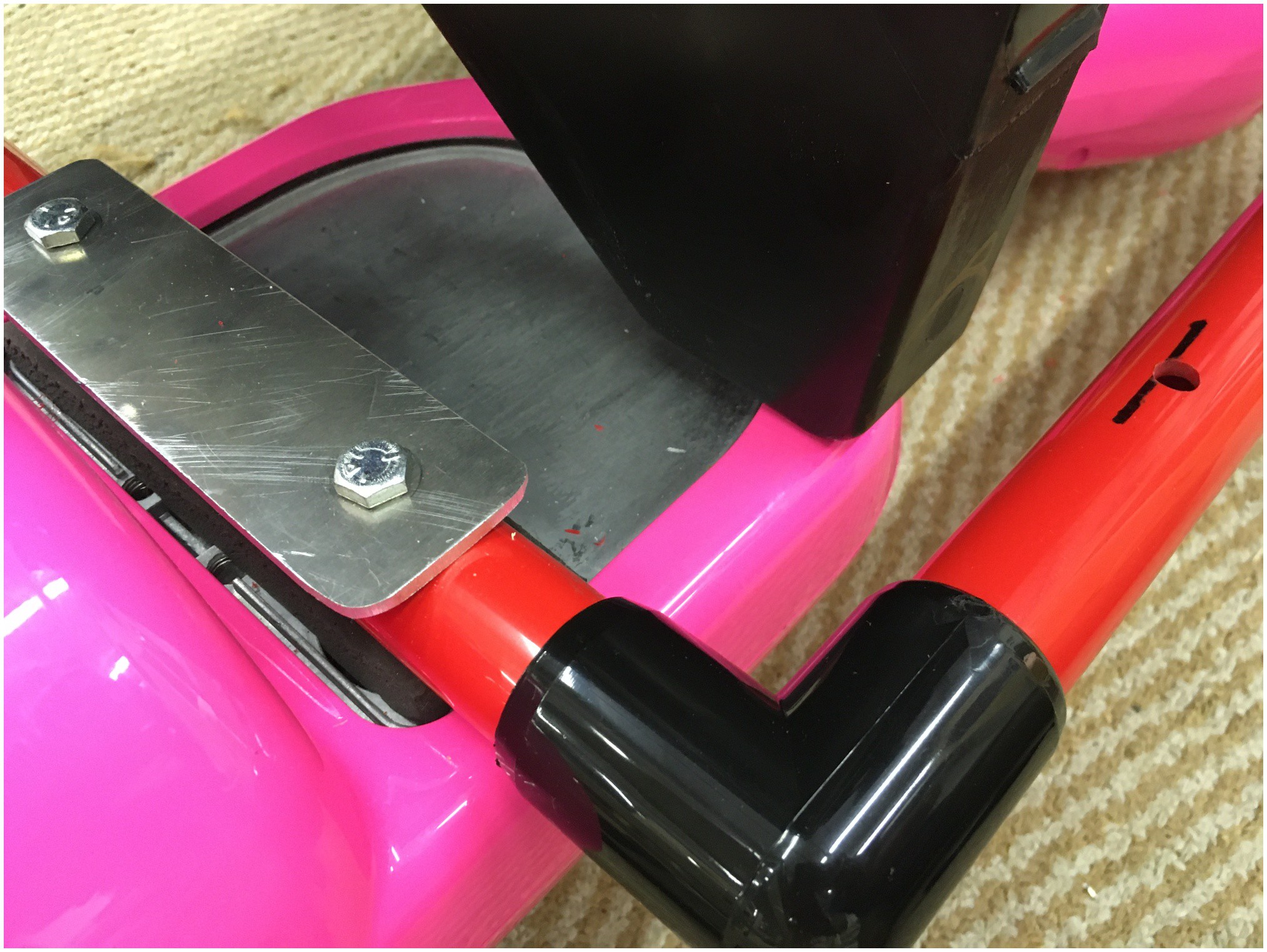
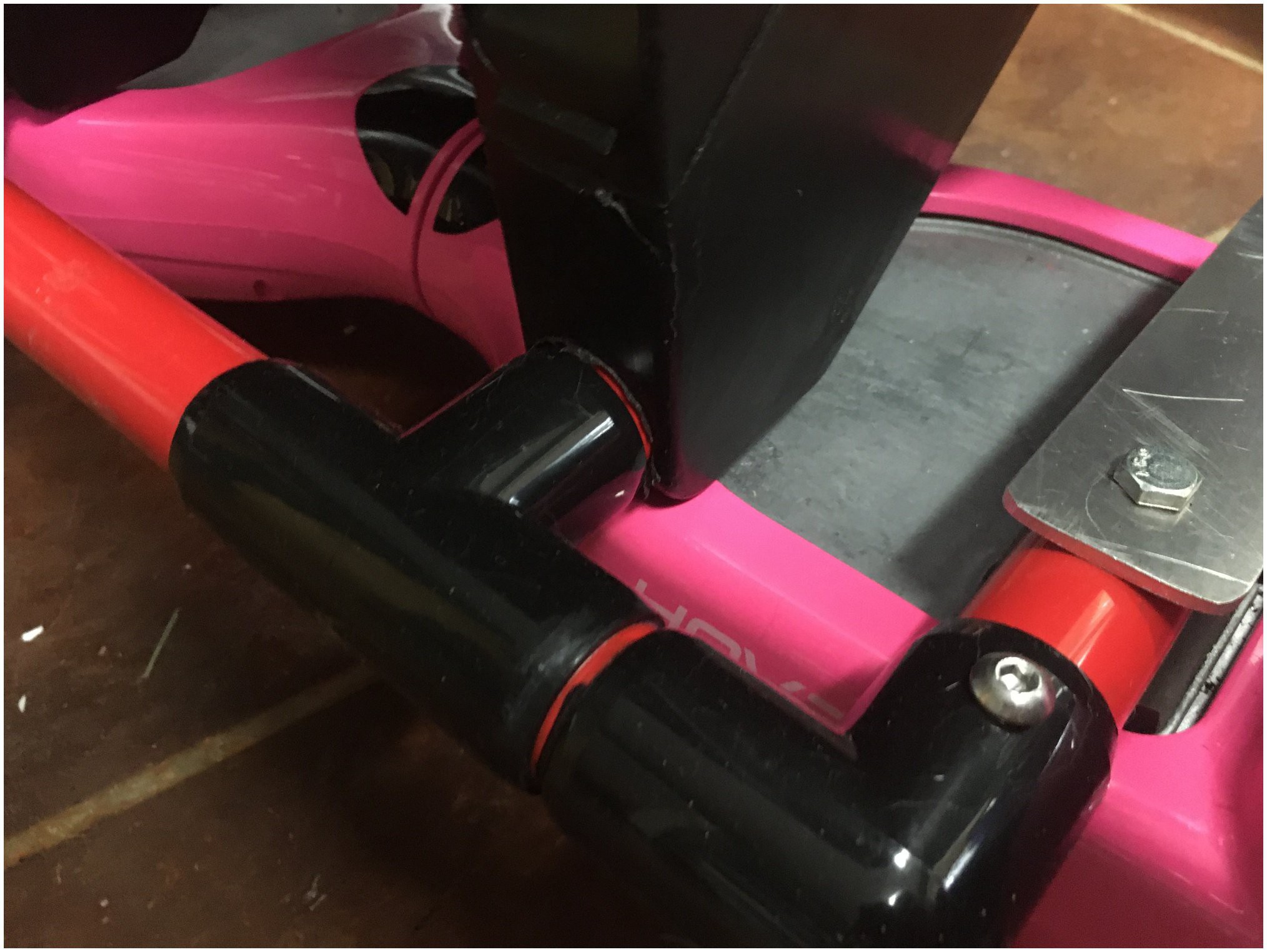
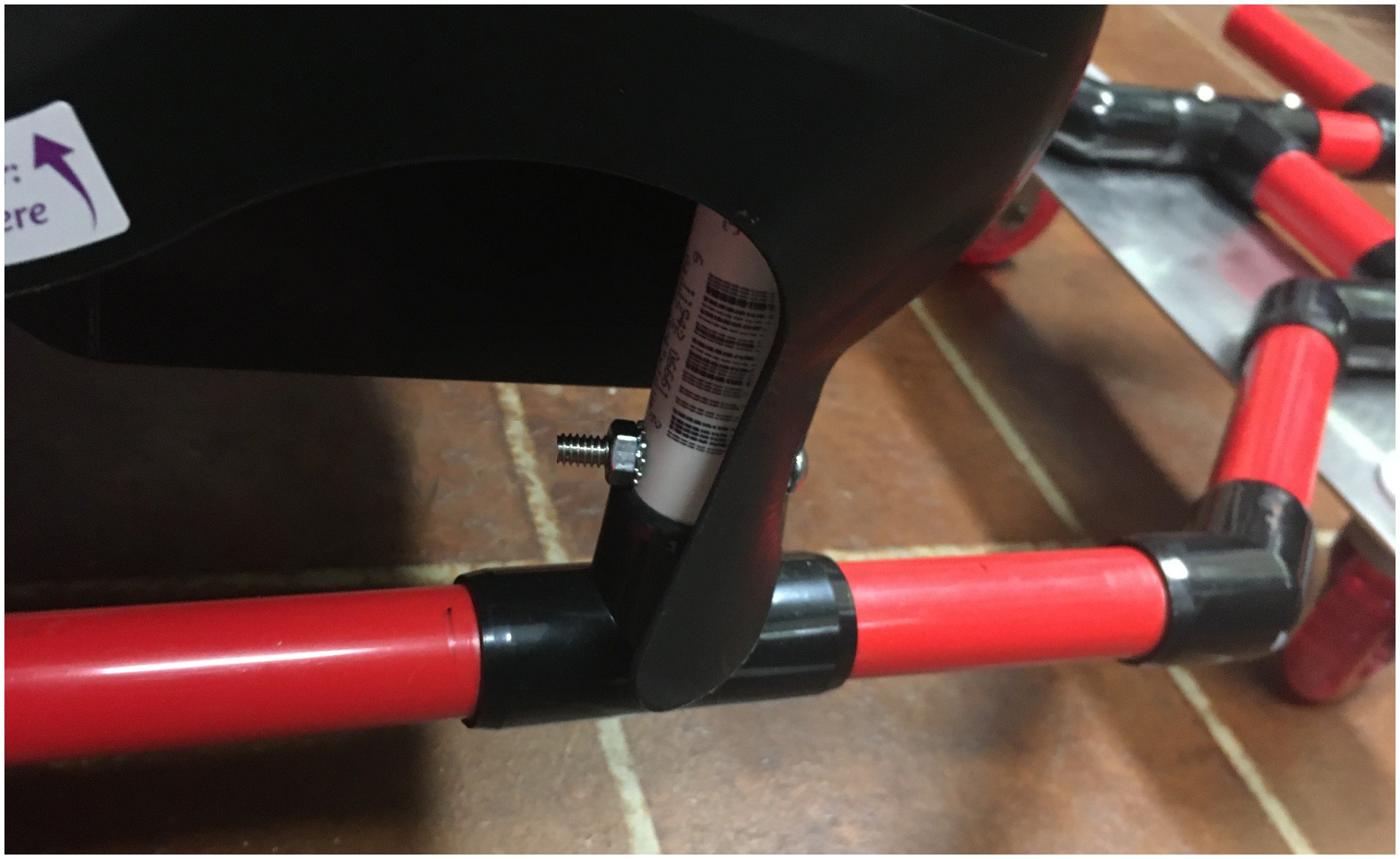
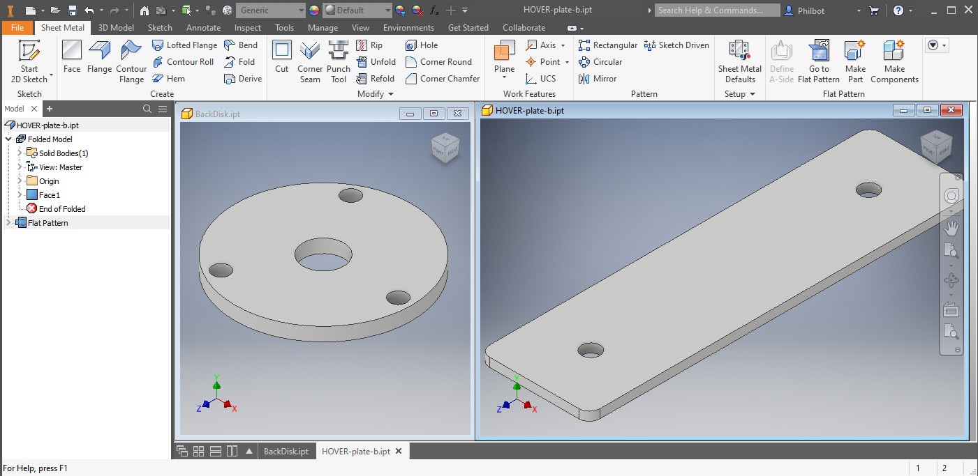
- Log #7 Mechanical Interface. 1st Gen.
- Log #8 Mechanical Interface. 2nd Gen.
- Log #9 BLDC Hybrid drive with "2-speed Shifter"
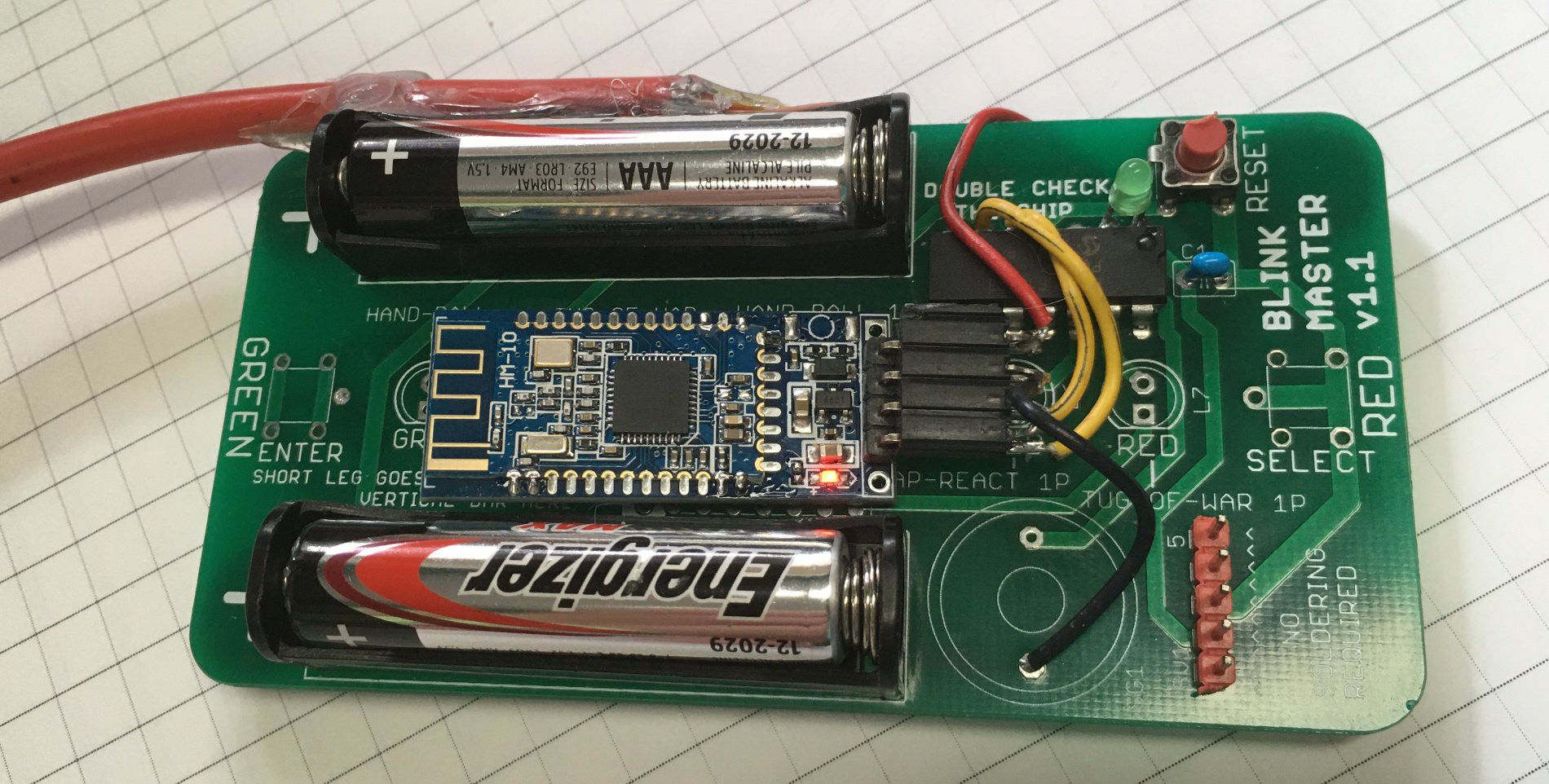
- Log #10 Wireless Control. Take 2
- Log #11 A new concept for a DIY Mobility Device.
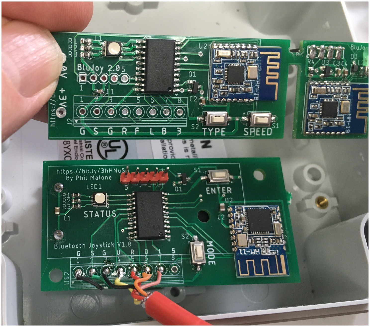
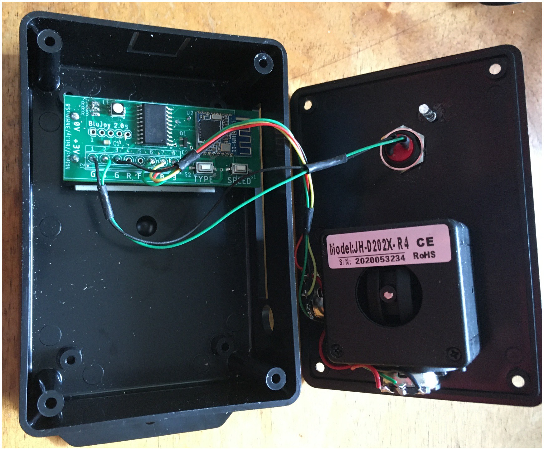
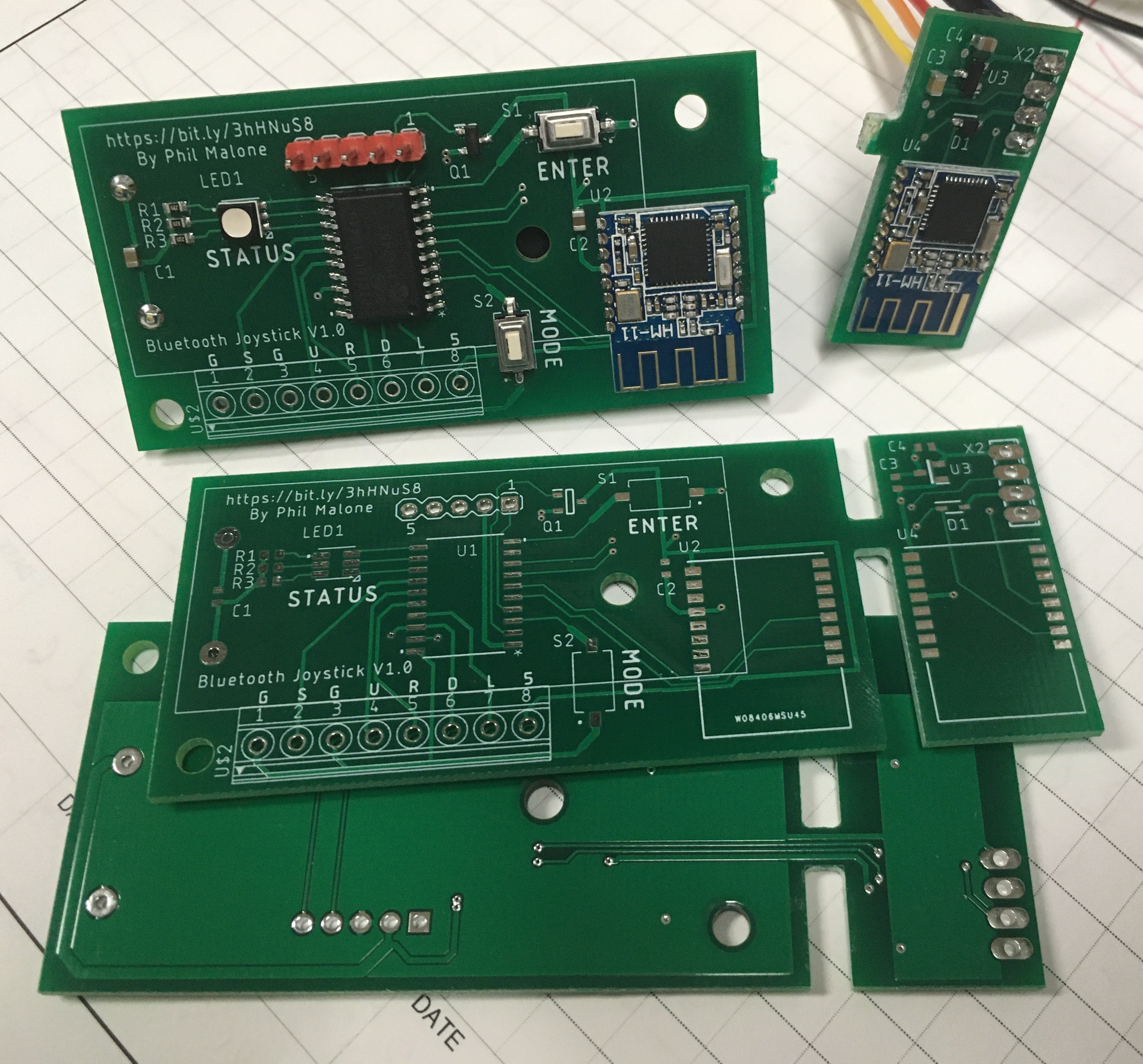
- Log #12 The "BluJoy" Bluetooth Joystick interface.
- 2020 Hackaday Prize review
- Log #14 Next Gen DIY Mobility Device.
- Log #15 New Joystick PCB testing.
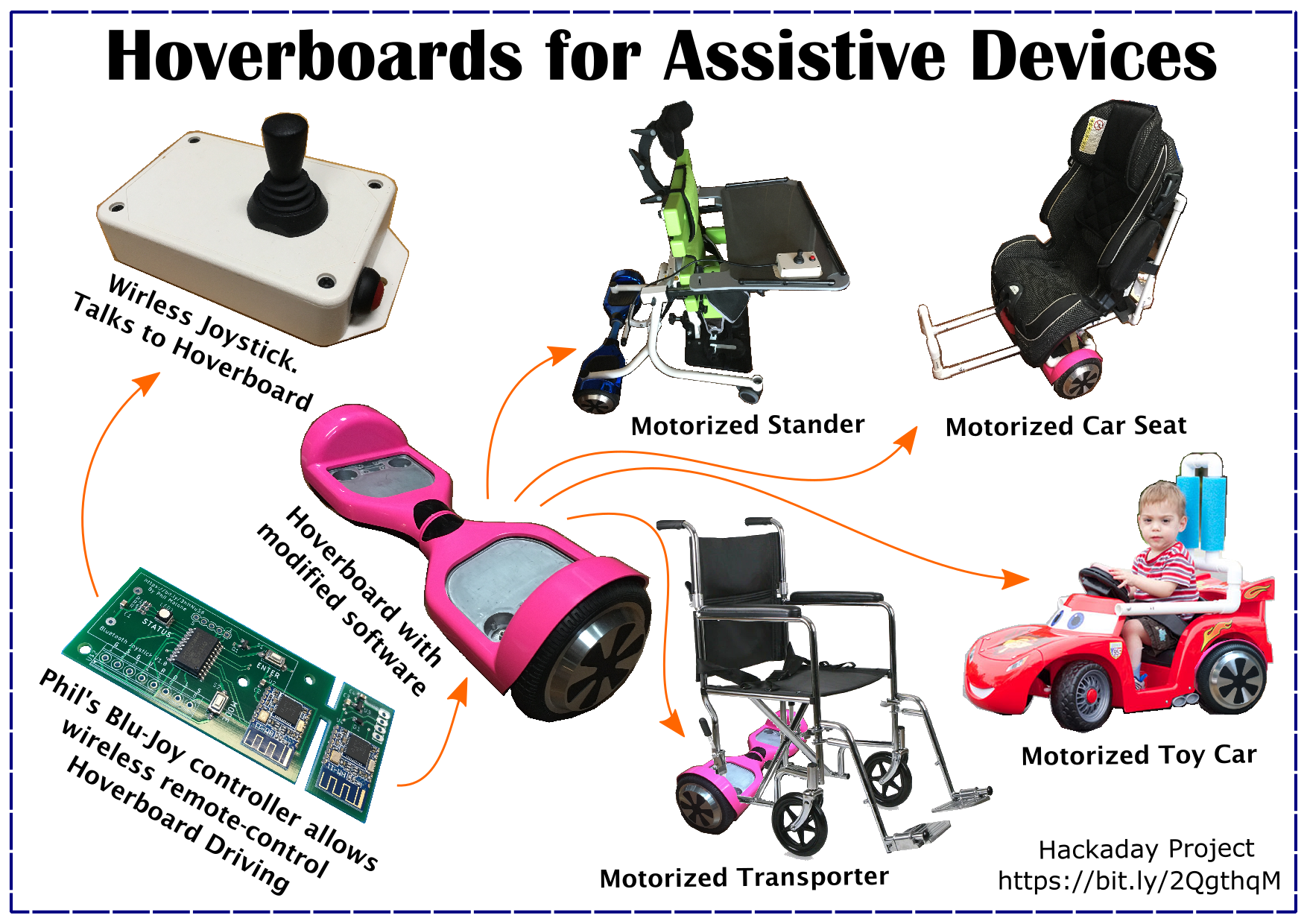
My goal here is to show that the concept of using a Hoverboard to motorize an adaptive transport system has a WIDE range of applications. Adding a power drive provides the user with new independence. No longer will they be at the mercy of someone to push them around.
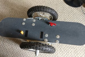
I want the formulae to be simple. 1) Beg, borrow or make a basic wheeled device. 2) Reprogram a Hoverboard to accept joystick commands. 3) Pick the best joystick for the user, and 4) combine all three items together.
I am creating simple and inexpensive solutions for 2) and 3). Along the way, I'll build some examples of how you can solve steps 1 and 4 on a case by case basis.
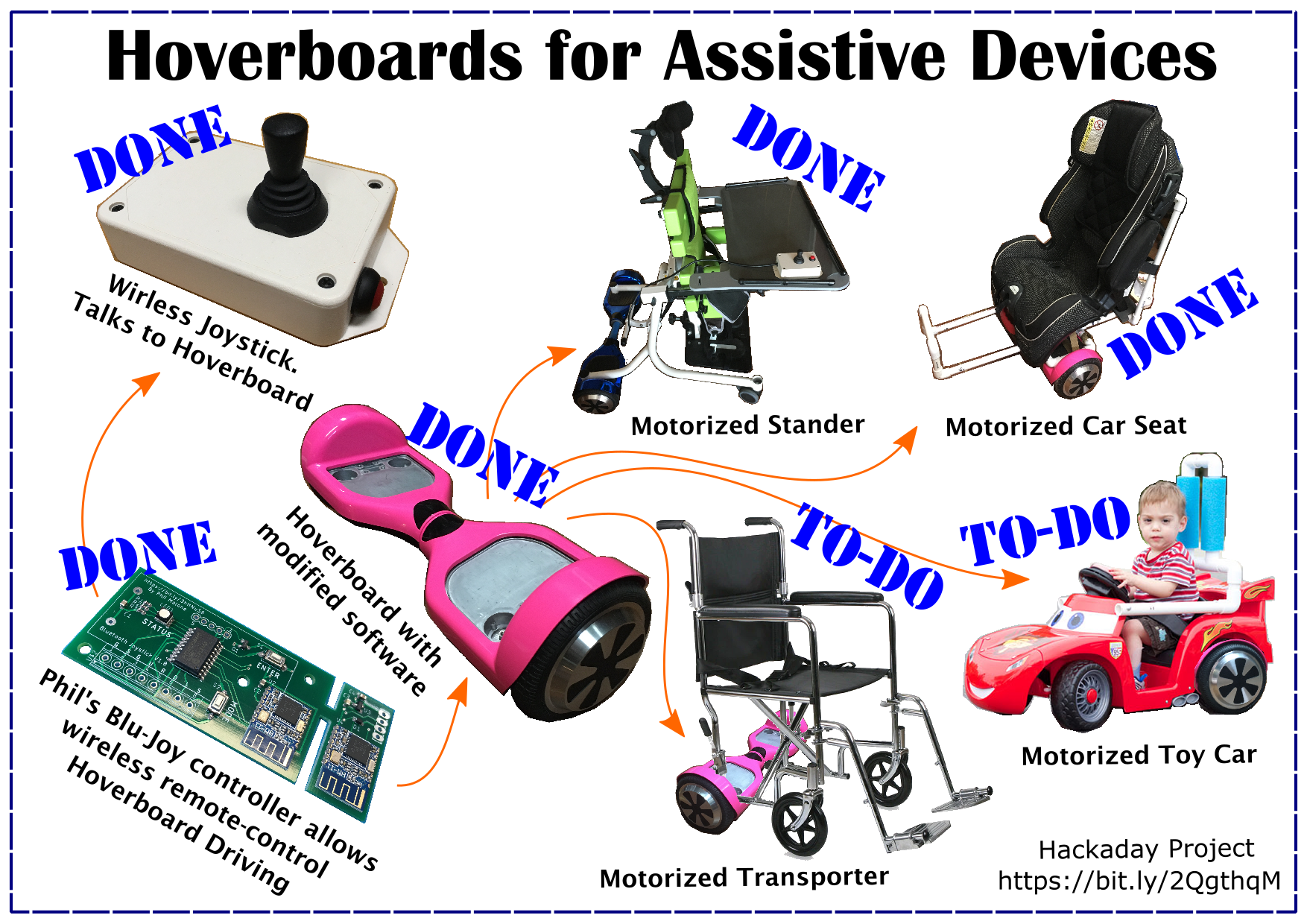
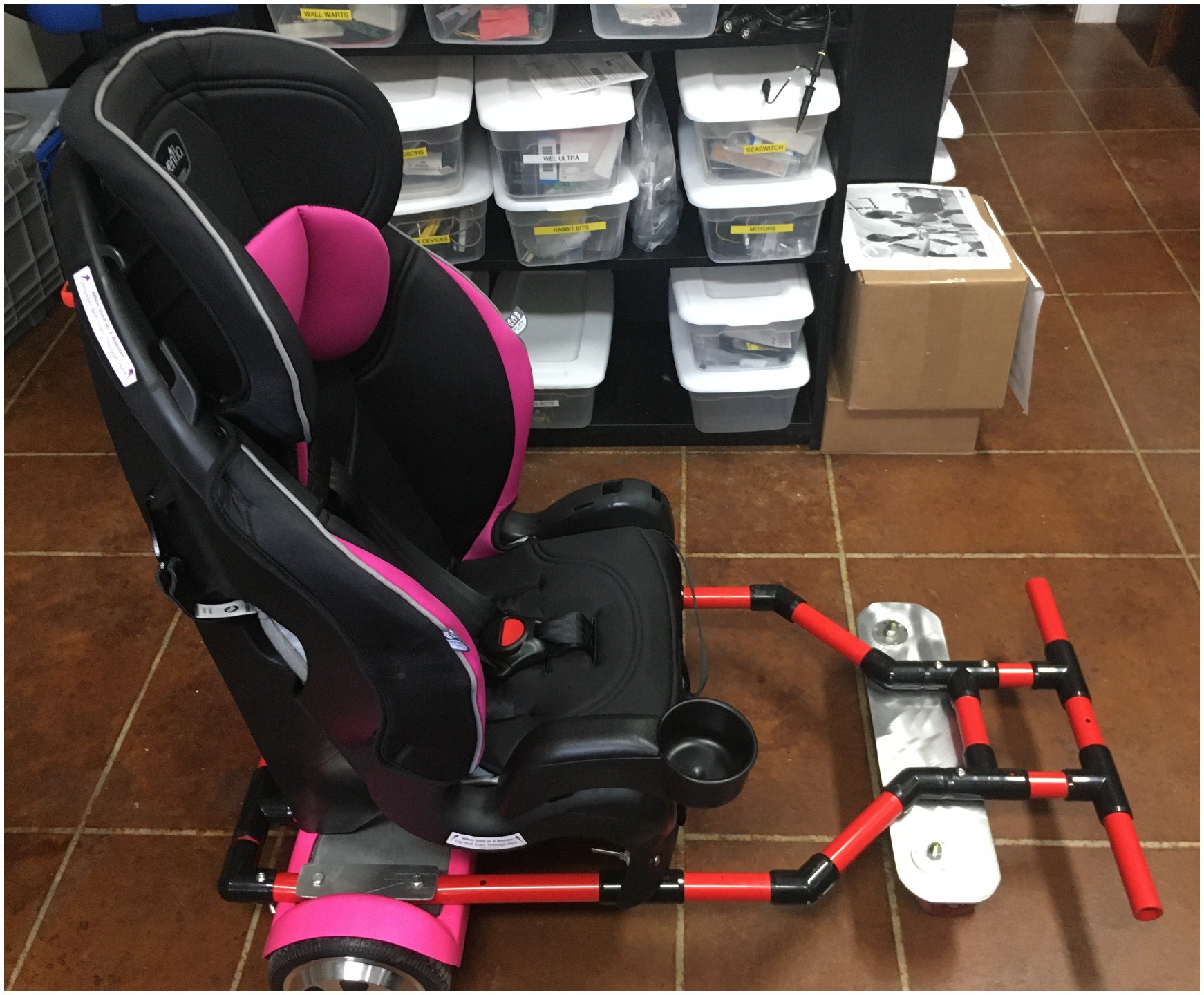
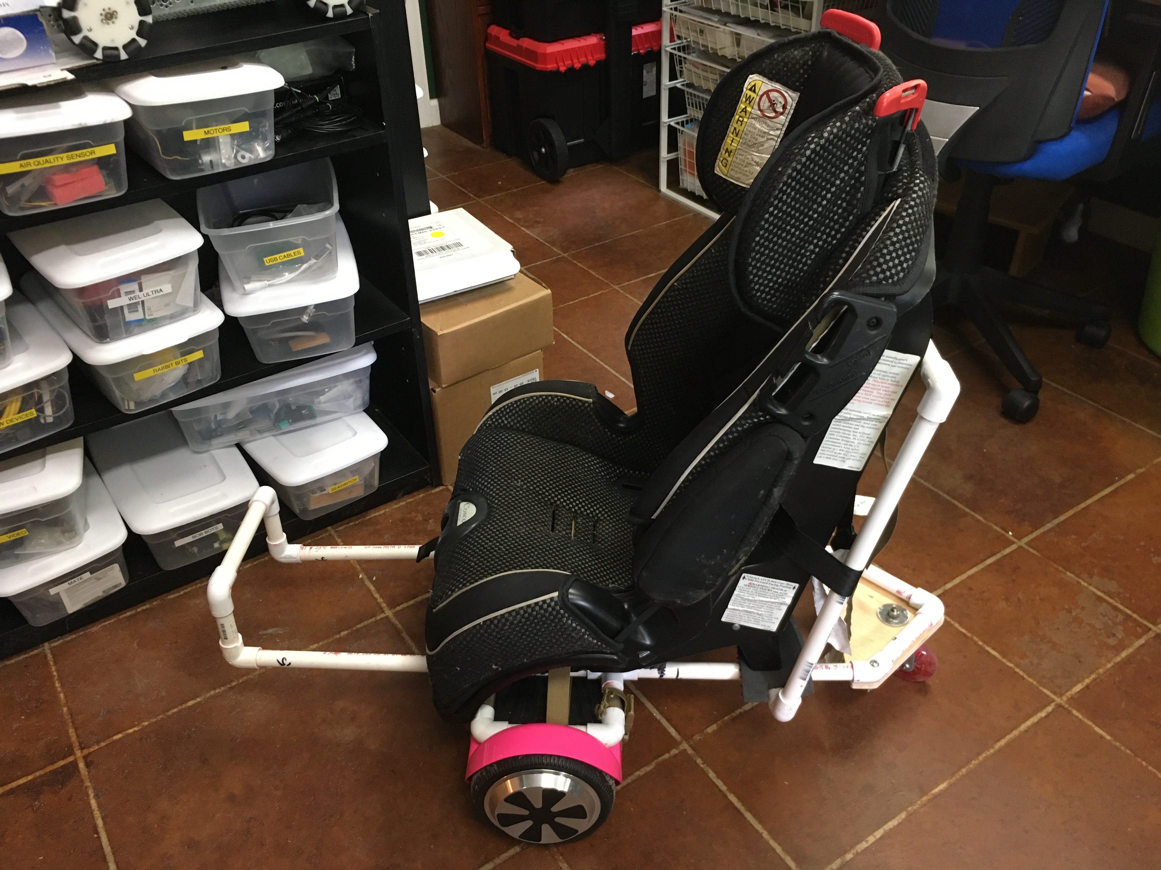
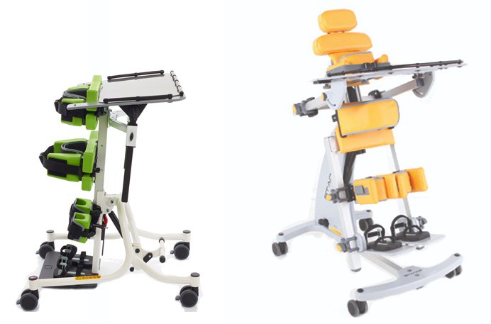
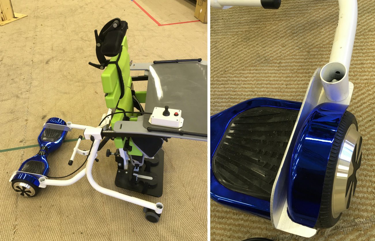
Currently I have two different prototypes. One is based on an expensive Jenx Multi-Stander , and the other is my own home-brew DIY concept. Both demonstrate using a hacked Hoverboard as their "drive" system. I used a hard-wired joystick for the stander, but then I developed a bluetooth Joystick interface for the newer DIY version.
Some teaser tech details:
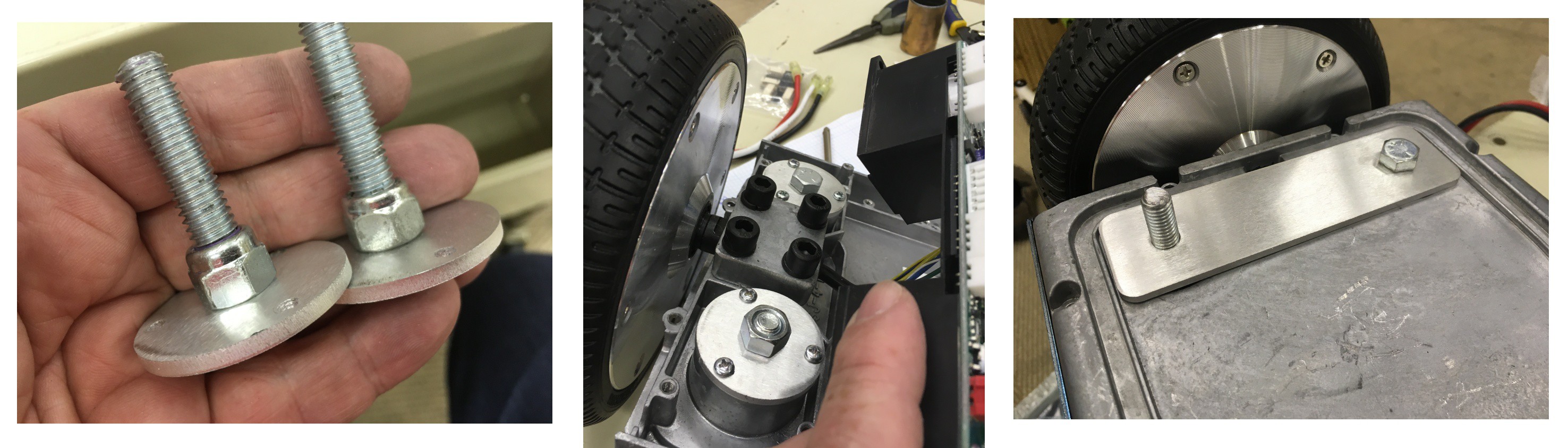
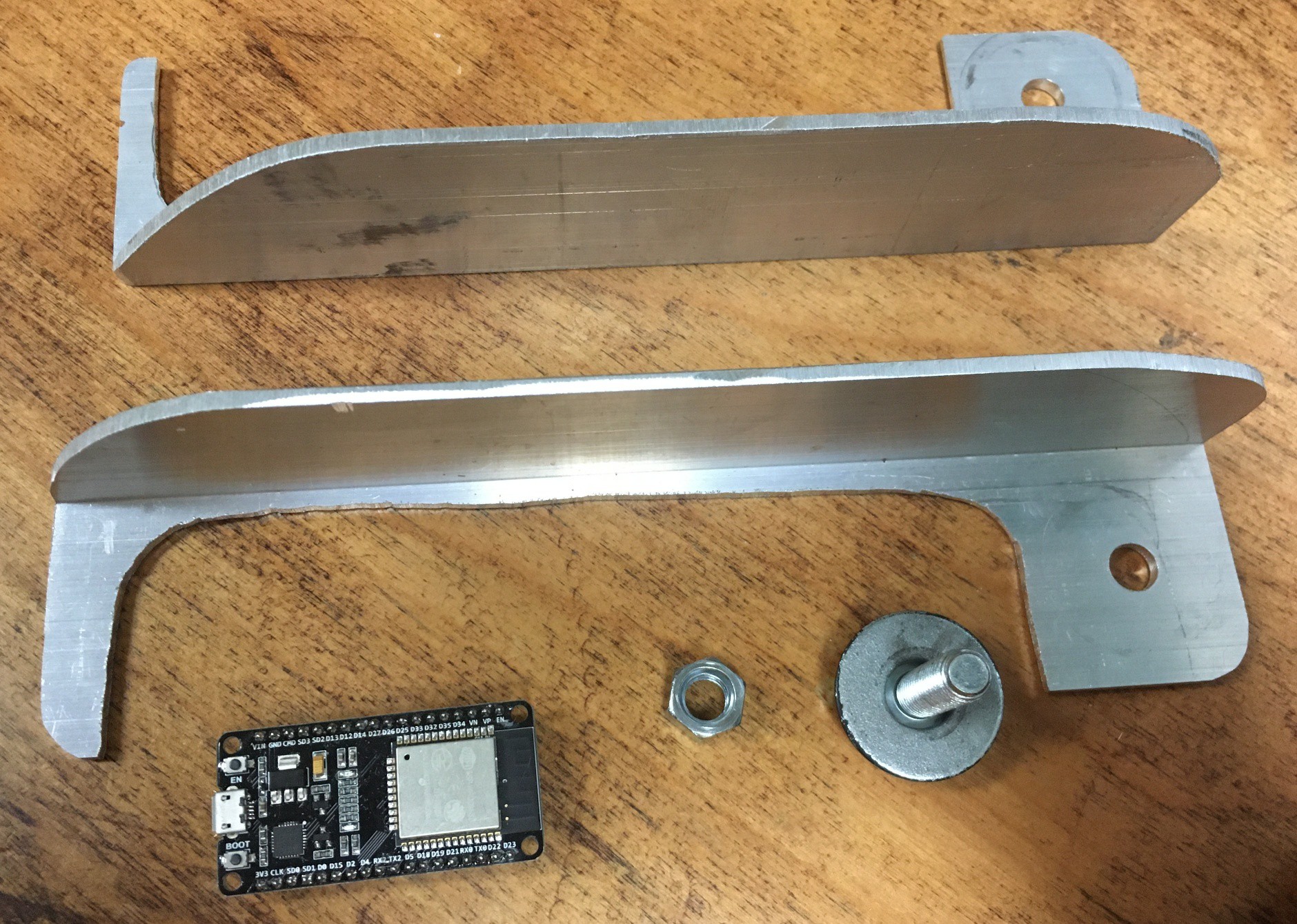
Both prototypes uses a HOVER-1 ULTRA hoverboard, running custom firmware on the 2 original Hoverboard Motor controllers. The first prototype has an additional embedded ESP32 based controller that interfaces with an external joystick, and generates motion profiles. The second prototype has a bluetooth module added to the hoverboard, which takes commands from a custom wireless Joystick controller.
My next task is to get some user feedback on the joystick motion profiles. I expect that I may have to play with acceleration rates, and time/velocity profiles for driving and turning.
I'm currently only using about 20% of the full velocity available, but the HOVER-1 ULTRA is still very controllable. I have implemented a simple P(ID) speed control to enable accurate speed across the full range of motion.


 Sam P
Sam P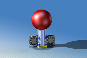
 Hardie
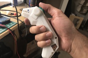
 Timo Birnschein
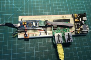
FYI, I was able to get V3.2 to compile by modifying a couple of calls but... later I found that somehow it interfered with the hall sensor pin. Everything else worked okay which confused me.