 hIOTron
About Project
The Zener diode is used to test batteries that have a voltage greater than 8v.

The 2.2k ohm resistor minimizes the current coming from the battery to something that the Arduino will be able to take in.High current may damage Arduino.
The circuit system also has three various LEDs, each of these LEDs shows how much charge there is left in the battery.
- Red will shows the battery is low/almost dead.
- Yellow will presents the battery being roughly half used up.
- The green will shows the battery being full.
We connect a 100-ohm resistor to each LED individually from the ground pin to the ground connection.
Circuit connection steps are mentioned below:
1. Wire the ground pin on the Arduino to the ground rail on the breadboard.
2. Put the three LED's respectively on breadboard and connect ground pins to ground rail.
3. Locate a 100-ohm resistor onto positive end of the LEDS then connect a wire from a resistor to the relevant pins on the Arduino.
The LEDs should connect to the relevant pin numbers as mentioned below:
- Red LED = 4
- Yellow LED = 3
- Green LED = 2
4. Now connect from analogue pin 0 (A0) to the breadboard. After this add a 2.2k resistor and the Zener diode. Connect a wire from other end of diode to the ground rail.
After setting all the connection and code, your project is ready for the testing.
Internet of Things Course Training is the way to implement your ideas and skills on various applications and projects.
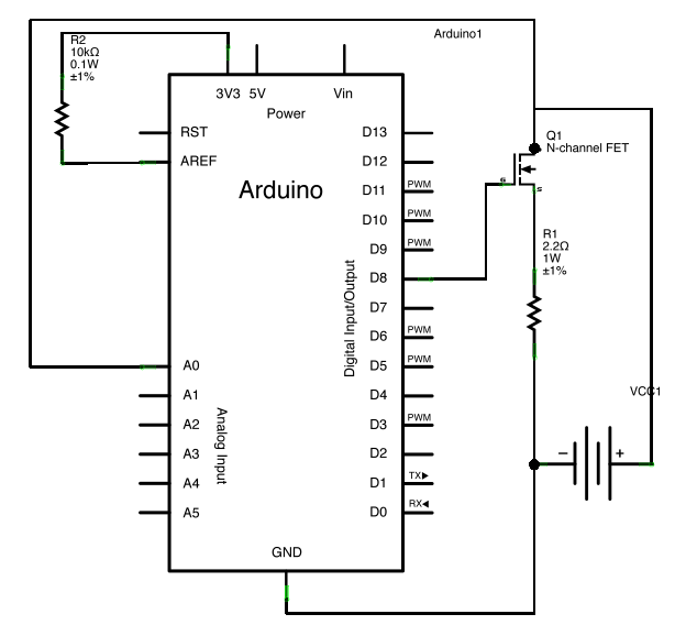
Schematics
Circuit Schematic
 electronicsworkshops
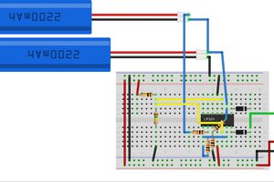
 Dave
Dave
 Bud Bennett
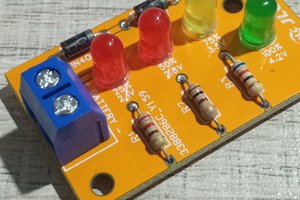
 ElectronicABC