A. J. Griggs
I bought a Behringer 15 watt amp and guitar from a young lad who'd had enough fun. I dumped the guitar, but kept the amp as a practice amp. Recently powering it on, I was greeted with a loud HUMMMMMM. "Oh, filter caps gone" I thought. On examination, the TDA2030 output chip had blown. These are obsolete, and you can get a clone from China, but I had a mono configured TPA3118 amp module lying around and maybe this could be used. And maybe a Class D amp would put out a few more watts than the Class AB TDA2030?
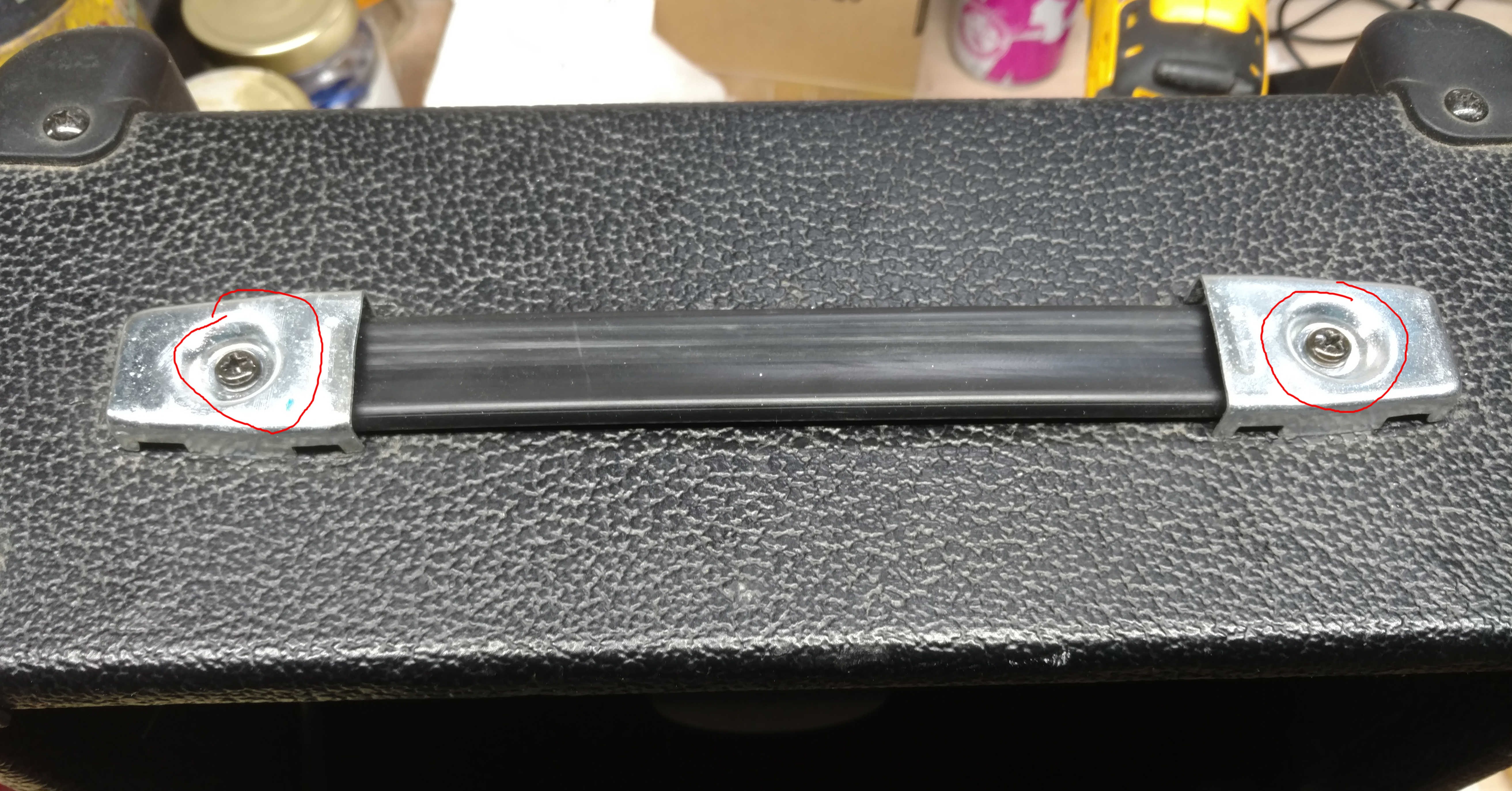
The Behringer is solidly built, and 4 screws (two on top under the handle covers and two at the rear) will open it up.
The front panel is held in place by the 3 1/4" jack nuts. Pull off the knobs and loosen the two screws for the chip heatsink and it comes free.
I planned to mount the tpa3118 module using the two tapped holes for the heatsink but of course those don't line up with any of the mounting holes for the module. You Could drill 4 holes and put in standoffs for the module, but I opted to 3d Printed carrier/adapter in ABS. Here's the carrier mounted in the chassis:
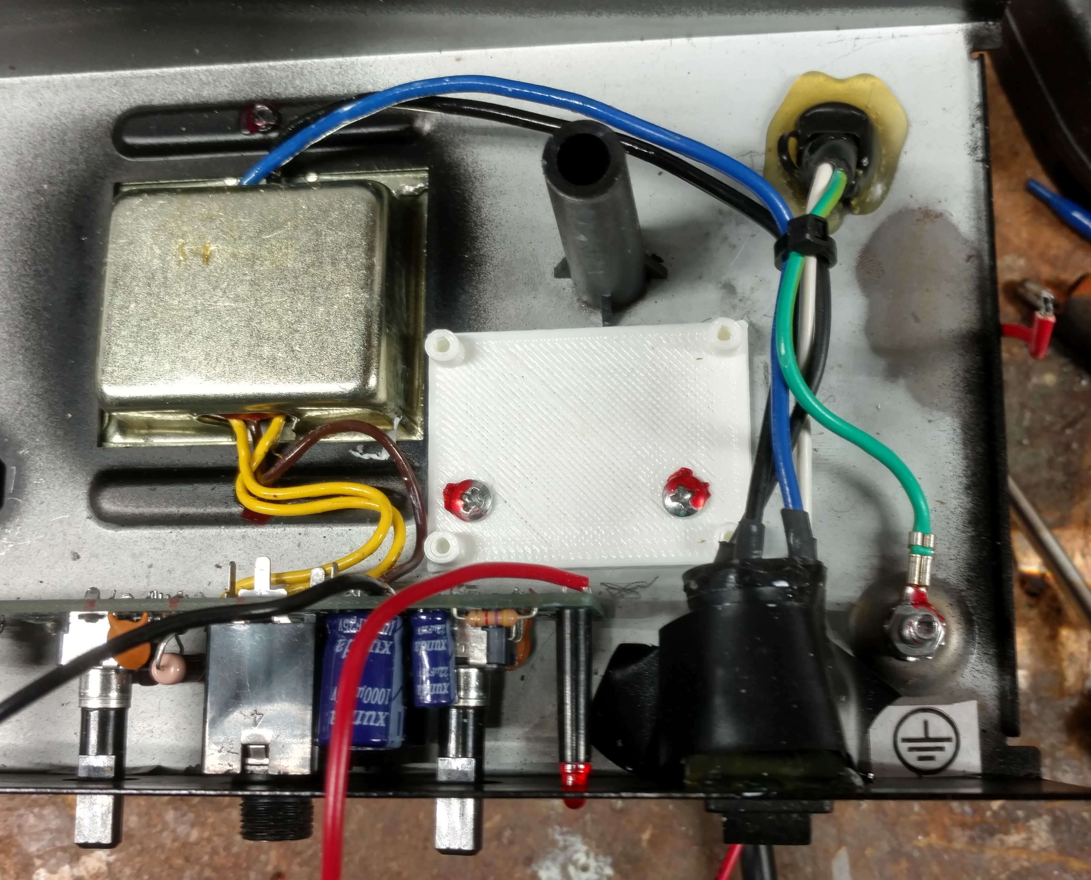
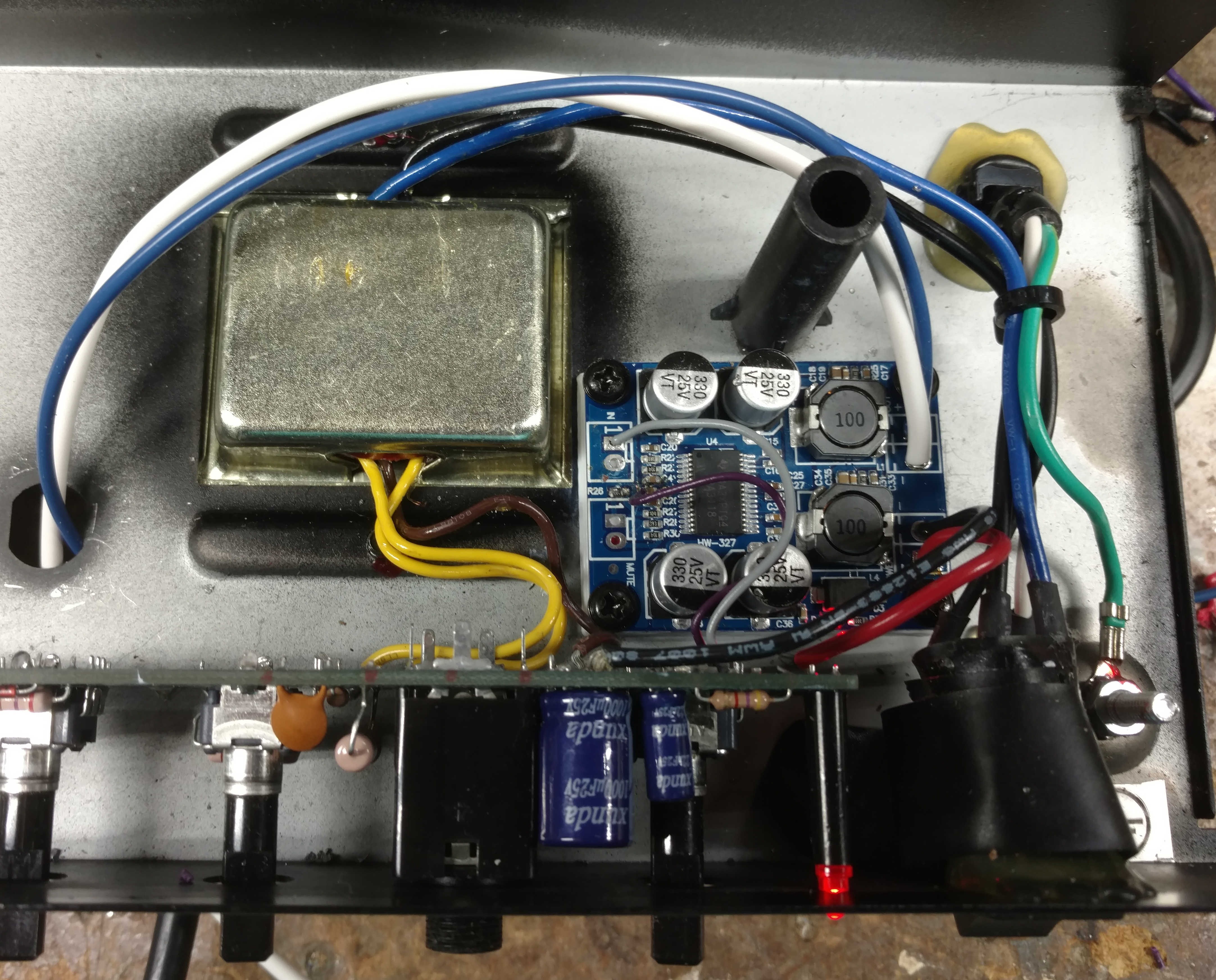
The TPA3118 can only withstand 30 Volts and typical applications have a max of 26 Volts. The FW bridge power supply in the amp is about +/- 16 volts unloaded. Only the +16 volt side was used. The module ground was made from the center-tap connection on the transformer and the +V connection came from the now empty +V connection for the TDA2030. The module -/+ inputs were tapped across the cold end and wiper of the Master Volume pot. I tried this and it worked ... sort of. There was a ground loop and the 120 hz hum was excessive. The TPA3118 has differential inputs, but the module builder connected the negative side to ground through a cap. This may be fine if you are using a regulated supply, but the amp supply was just a rectified filtered output and the ripple currents running through the output ground were evident.
So .... I removed the negative input cap connected to pin 5 of the chip (RINN) and chopped out the connection to ground. I replaced the cap and Carefully soldered a (-) input wire the now unconnected end of the cap. Snarky, but it worked.
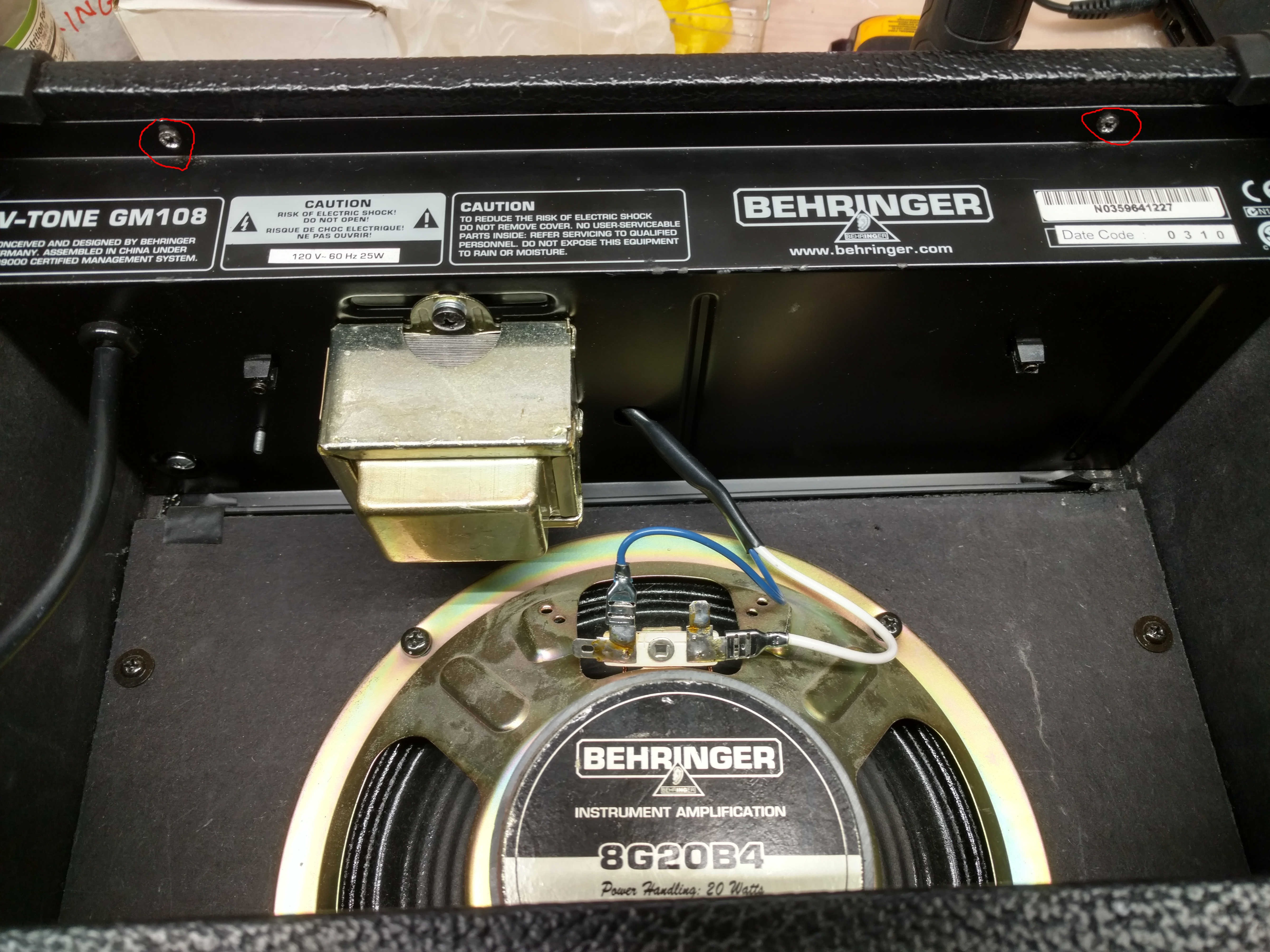
Testing showed that the + supply dipped to about 14 volts under heavy load. I measured a maximum output of about 20 watts into 4 ohms before clipping. Here is the wired module in the amp chassis:
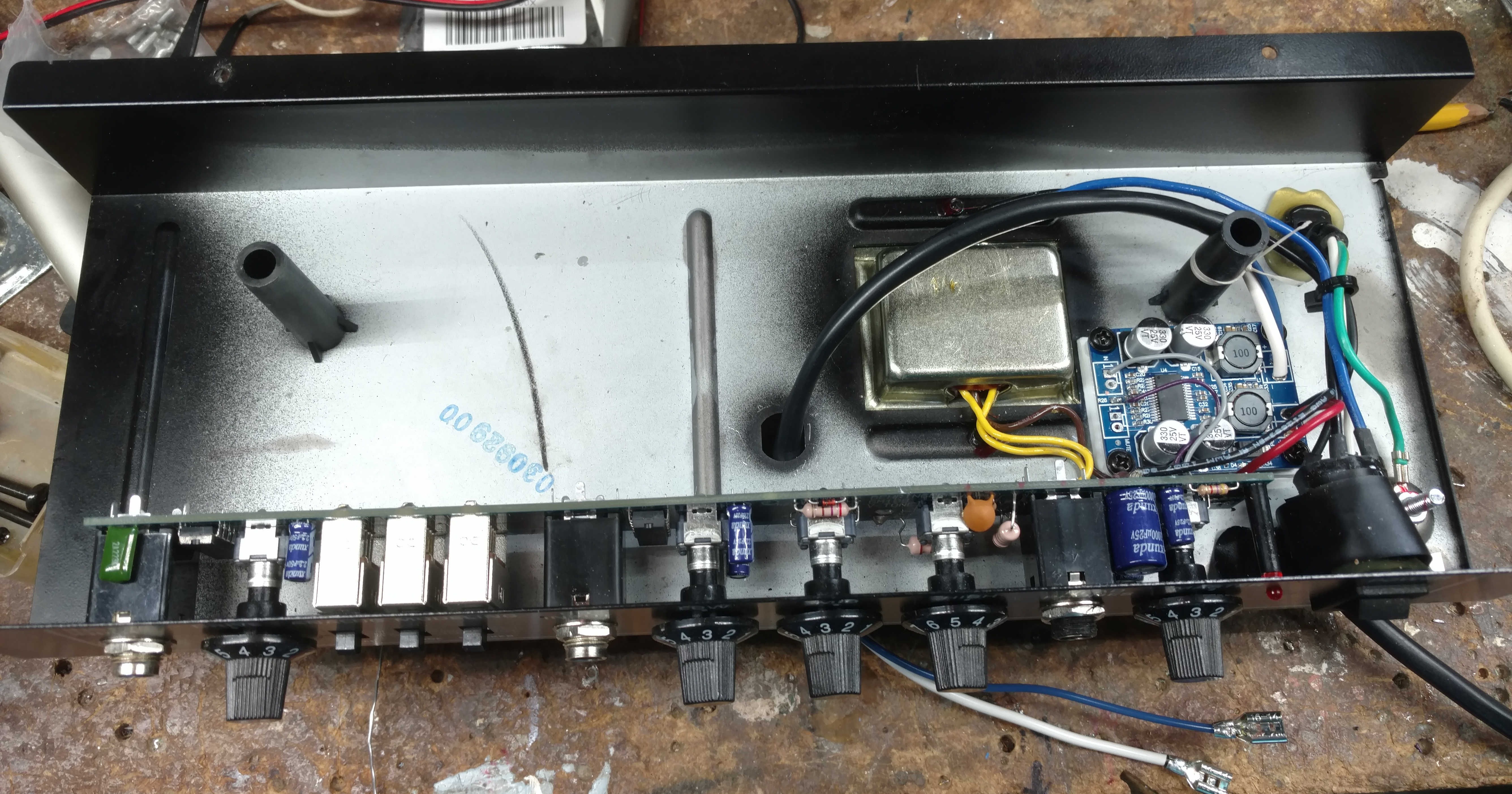
Before I closed it up, I secured the white/blue output wires to the mounting screw pass through post.
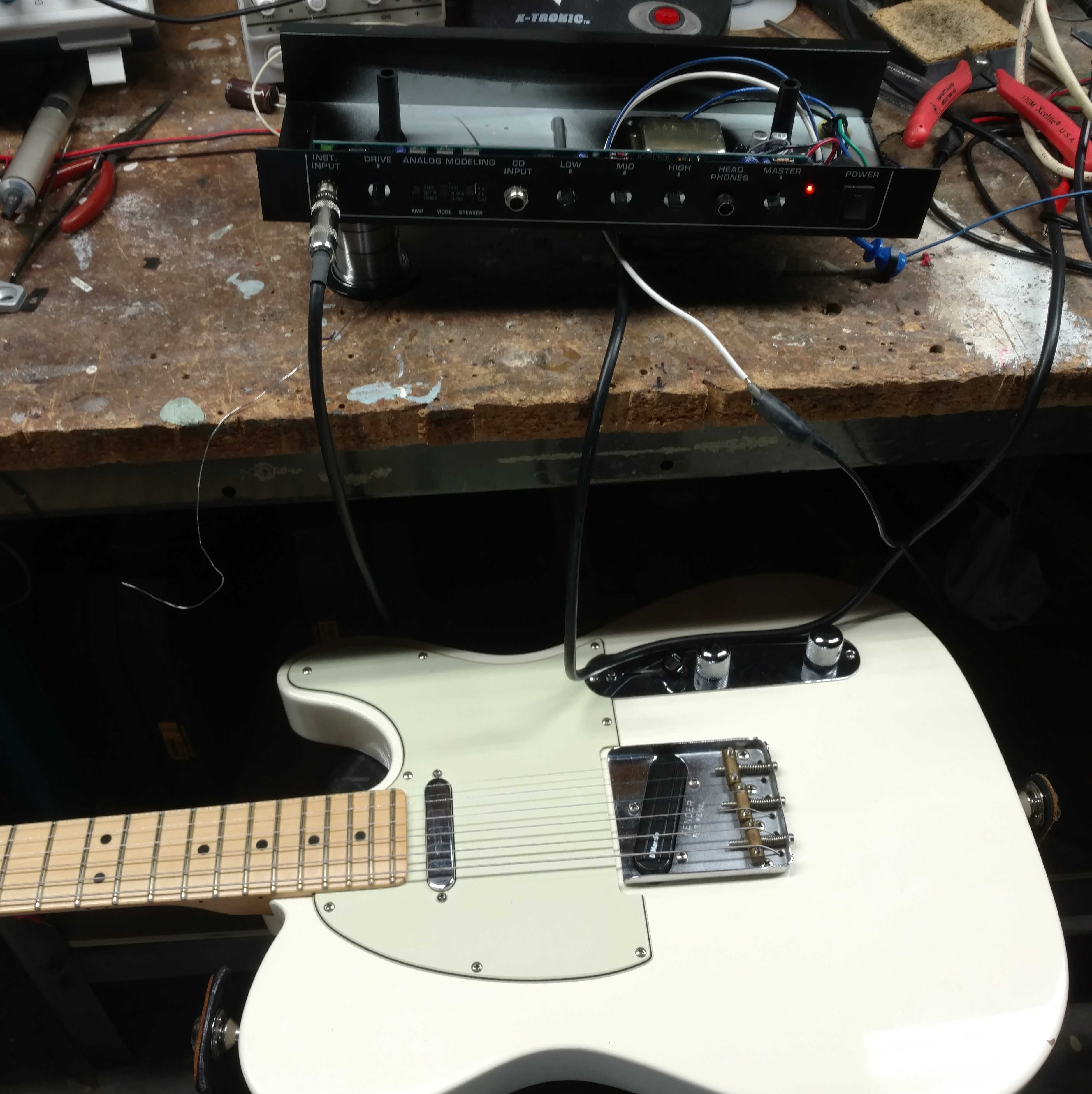
Testing... 1 2 3
All neat and tidy (the amp, Not my bench) and ready for installation. I added push-on connectors for the speaker instead of hard soldering as in the production version.
It works. There is a small hum which is not noticed at all with any reasonable playing volume. There is also a pop on power up when the Master Volume is not at zero. I'd have to say overall I'm happy with the result. I was surprised by the quality of the analog distortion modeling. No where near what my Fractal AX8 can do, but usable.
Upgrades: I considered adding filter capacitance to the + output to hold up the supply during transients (pick attack), but the 4x330uf caps on the module do a fair job of helping the 1000 uf cap on the original amp. How about reducing the voltage drop with Schottky diodes on the + output? A few tenths of a volt and not really worth it. A bigger transformer? A Warehouse replacement speaker? Wait! This is a crummy little 15 watt amp. The cheapest thing to do is buy a clone TPA2030 and put it in! But, the speaker might be nice. The midrange 'honk' of this speaker/cab setup is a bit annoying. Maybe I should just make a board that does what I want with simple FX like reverb,chorus and delay? No no no ....
Have fun!
ajg
 Neil Mundt
 Maxim Fyodorov