 benw
benwWell I'm one happy guy the Adaptive Interface Module has been designed, assembled and tested without any issues or board mods. So lets start off the project log story with the following:
How did I assemble the double sided boards?
Whole I don't have a PnP machine (yet) I've been assembling the boards by hand with some help of a solder stencil, a reflow oven and finally a SMD stencil (which I discussed in a earlier post).
Now some of you might be wondering how I soldered both sides using solder paste.Normally in mass manufacture they would use epoxy glue dots to hold down components during double sided manufacture. But this a costly and takes time. There is another method that can be used which is great for prototyping and it simply uses two different reflow temperature solder pastes.
To assemble the PWA the following equipment and tools are required:
- Bare PWA.
- Solder Stencil.
- Solder Paste distribution (Any card will do)
- ESD Strap and ESD Mat.
- ESD Tweezers.
- Reflow Oven (Home made or commercial version)
- Solder Paste (See below)
- A Steady Hand (Tea or Coffee might be required)
- Optional SMD stencil for QFN packages.
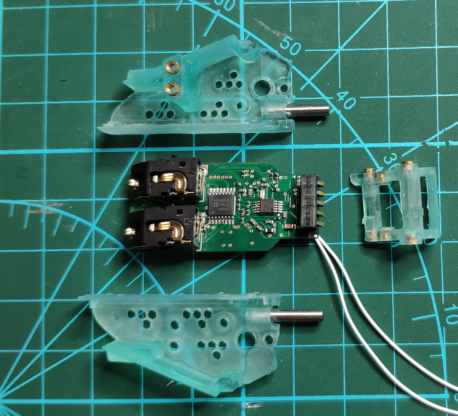
A view of the finished boards are below:

Solder Paste Tip for Double Sided Assembly:
My tip for assembling a double side PWA's is to use two different solder paste's. My go to choices are:
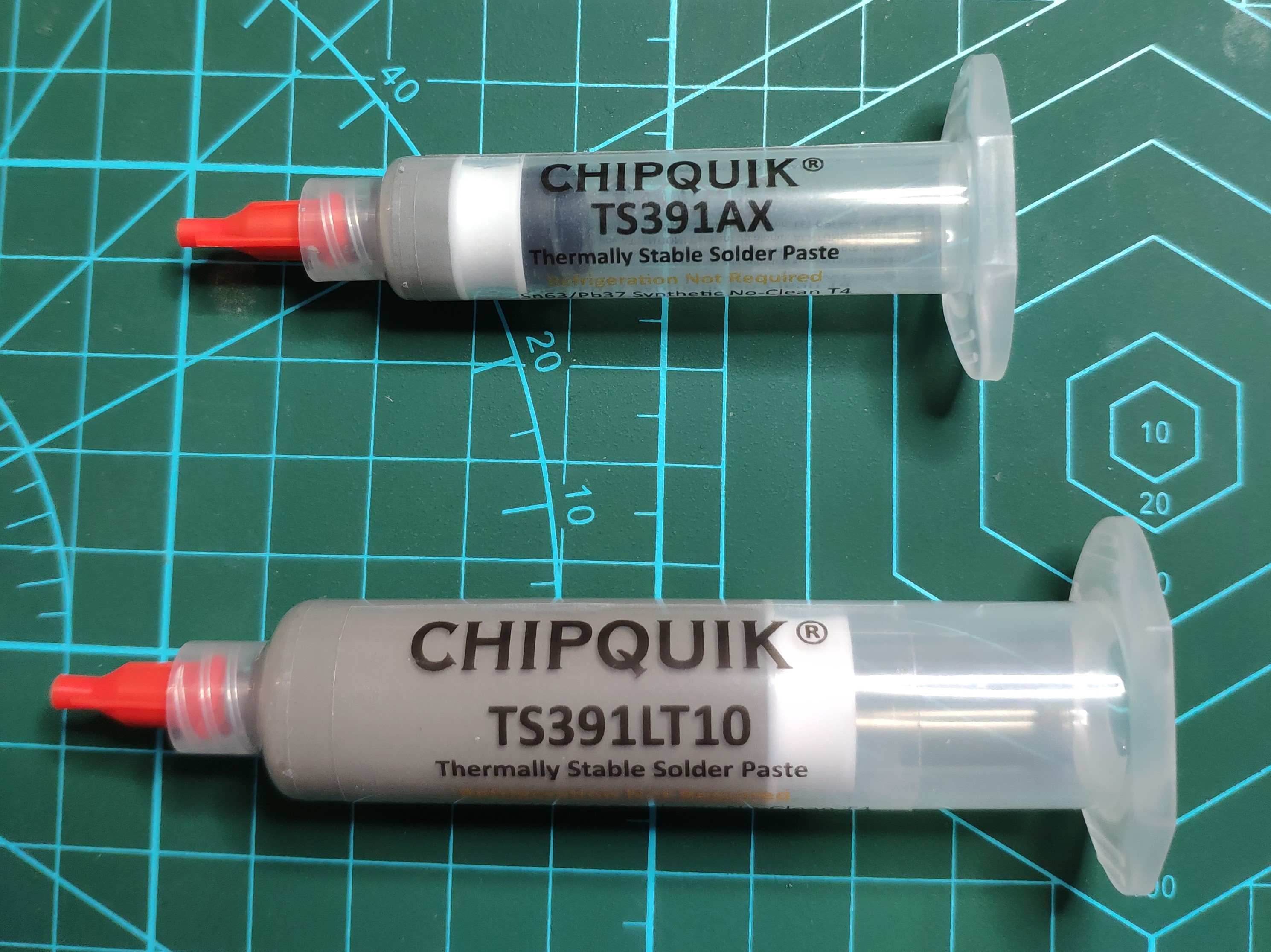
- TS391AX > Reflow Temp= 235c
- TS391LT10 > Reflow Temp= 165c
The idea is that you with first use the higher temperature solder paste on the less critical comportment side, which in my case was the top side. After reflowed these parts will remain in place during the last pass using the lower temp solder. which was applied to the bottom side. After this you will have a nice double sided assembled board.
Ready For Module Assembly:
After PWA assembly the debug UART wires were connected to aid in firmware writing and testing. All that was left is to screw the module frame into the PWA and the module is ready for firmware development.
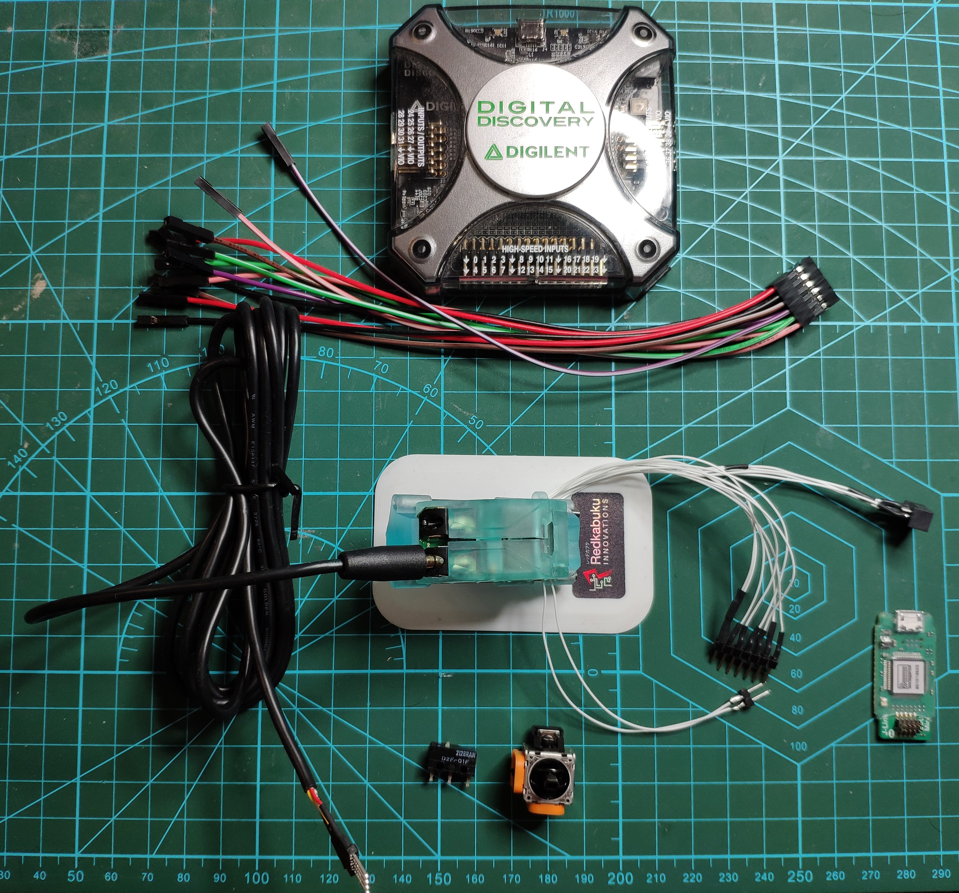
What was my setup for firmware development and testing?
Most of the modules use the same elements for testing which are the following:
- Digital Discovery Signal Analyser+ leads
- Jlink EDU Mini
- RX-Modules Debug Station
The completely test the adaptive interface the following extra are required:
- 3.5mm 4 Pole Audio Cable to flying leads.
- Simple Push Button
- Joystick, 10K Pot Version
Firmware Test Results: Pass with flying colours and fully supports Microsoft adaptive controls and any open source controls. A full specification will be written.
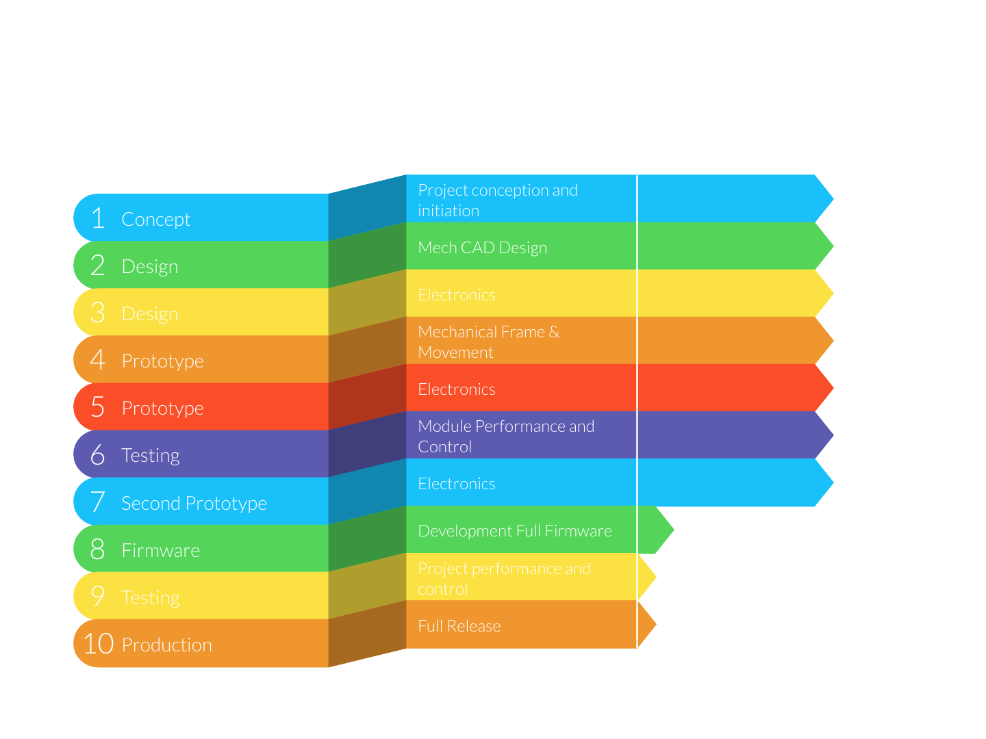
Progress:
Currently in Full Firmware Development.
What's Next?
As the Adaptive Interface Module has passed both hardware and firmware testing the following can be sent for manufacture:
- Touch-D Module Core.
- SMART Scroll Core.
Both these core's share common circuity and routing to the Adaptive Interface Module Core.
Apart from that the following are due to be assembled in the next couple of days:
- High-P Core
- Dev Interface PWA
Keep watching the project logs for more exciting news.
All the Best.
Discussions
Become a Hackaday.io Member
Create an account to leave a comment. Already have an account? Log In.