 DIY GUY Chris
This project is so handy to make specially after getting the customized PCB that we’ve ordered from JLCPCB to improve the appearance of our electronic device and also there is enough documents and codes in this guide to assist you create your beautiful robot.
We've made this project in just 5 days only, just two days to get the robot 3D printed parts all the needed electronics components then two more days to finish the hardware making and the assemble, then one day to prepare the code to suit our project and we have started the testing and the adjustments.
What you will learn from this instructable:
- Making the components selection depending on its functionalities.
- Understand the robot mecanisme.
- Prepare the circuit diagram to connect all the choosen components.
- Solder the electronic parts to the PCB.
- Assemble all the project parts (robot body).
- Start the first test and validate the project.
Step 1: How This Robot Works!

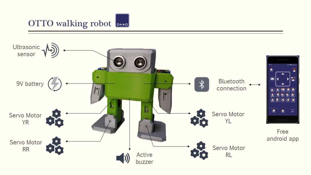
Starting with the project description, as I said already, we will reproduce the OTTO robot model that you can have its 3D designed parts for free from the OTTO community but what we will add in our project is a customized PCB design to control the robot so we will use the ATmega328 microcontroller instead of using a whole Arduino Nano board the way the community did for this project.
The robot has many features and you will like its movements performed by 4 servo motors and its sounds diplayed through an active buzzer, the robot will be powered by a simple 9V lithium battery and controlled by a Bluetooth module through an android app that you can download directly for free from playstore and appstore.
The robot movements are performed by 4 servo motors so we have 2 servos in each leg and also there is an upgraded version of the OTTO robot to control the hands movements too but we will not do this in this instractable and we will upgrade the controle board for this task in our coming instructable.
Step 2: Circuit Diagram

In order to gather all the electronics components together I chose to create my own PCB design for this project and produce it from JLCPCB, I moved to easyEDA platform where I prepared the following circuit diagram and as you can see all the components that we need, then I transformed the circuit design into a PCB design with the required dimensions to fit the robot chassis.
Step 3: PCB Making
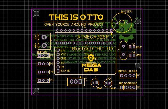


After preparing the circuit ,I transformed it into a customized PCB design with the reuired dimentions and shape to suit our robot chasis. The next step is generating the GERBER files of the PCB design and upload it to JLCPCB order page to produce our PCB.
Four days to wait for the PCBs and here we are. This is the first time we try the yellow color for the PCBs and it really looks so great.
Step 4: Robot Body 3D Printed Parts
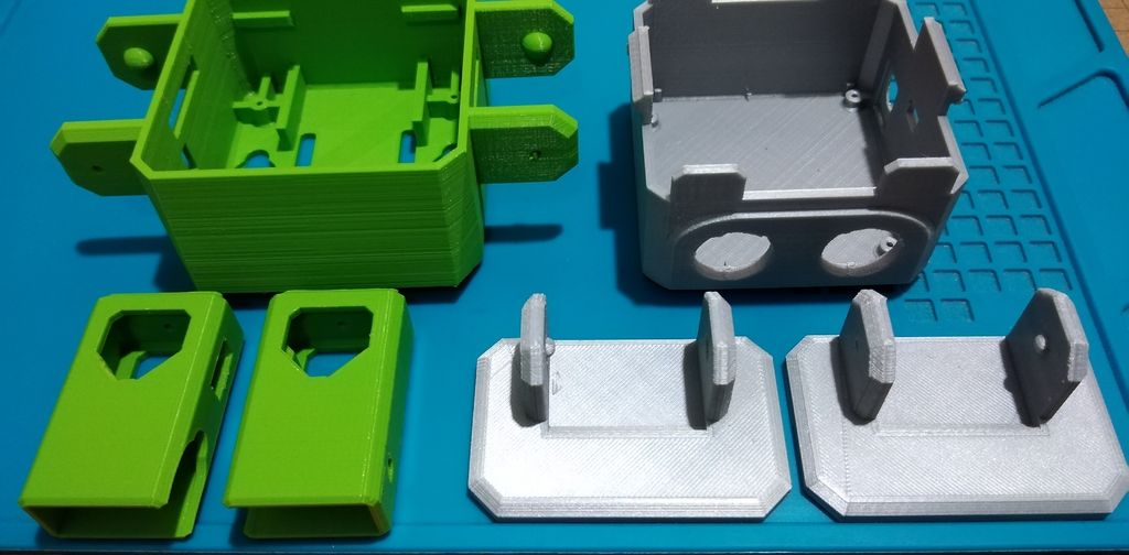
Moving to the robot body parts, as I already mentioned in the presentation you could have the STL files of this robot from the OTTO community website through this link in order to produce these parts through a 3D printer.
Step 5: Electronic Ingredients
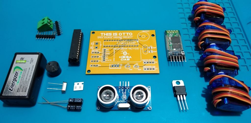
Now we have everything ready to go so let’s review the components list:
★☆★ The necessary components (Amazon links) ★☆★
- The PCB that we have ordered from JLCPCB
- ATmega328 microcontroller : https://www.amazon.com/gp/product/B07PZWYW2F/ref=...
- HC-05 Bluetooth module : https://www.amazon.com/gp/product/B01G9KSAF6/ref=...
- Ultrasonic sensor : https://www.amazon.com/gp/product/B01G9KSAF6/ref=...
- 4 servo motors : https://www.amazon.com/gp/product/B01G9KSAF6/ref=...
- 22pF capacitors : https://www.amazon.com/gp/product/B01G9KSAF6/ref=...
- 10uF capacitors : https://www.amazon.com/gp/product/B01G9KSAF6/ref=...
- An oscillator : https://www.amazon.com/gp/product/B01G9KSAF6/ref=...
- L7805 Voltage regulator : https://www.amazon.com/gp/product/B01G9KSAF6/ref=...
- A buzzer : https://www.amazon.com/gp/product/B01G9KSAF6/ref=......

 Carl Bugeja
You made it look easy! THANKS!