0%
0%
BLE Midi controller conversion of NI KORE
Converting the Native Instruments KORE controller to a BLE/USB MIDI control surface
Become a Hackaday.io member
Already have an account? Log in.
Just one more thing
To make the experience fit your profile, pick a username and tell us what interests you.
Pick an awesome username
hackaday.io/
Your profile's URL: hackaday.io/username. Max 25 alphanumeric characters.
Pick a few interests
Projects that share your interests
People that share your interests


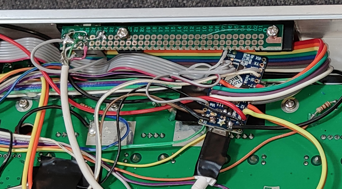
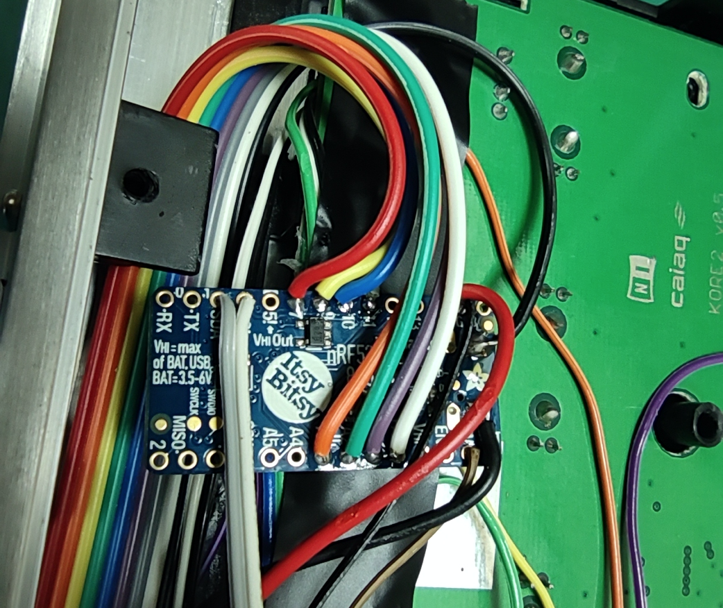
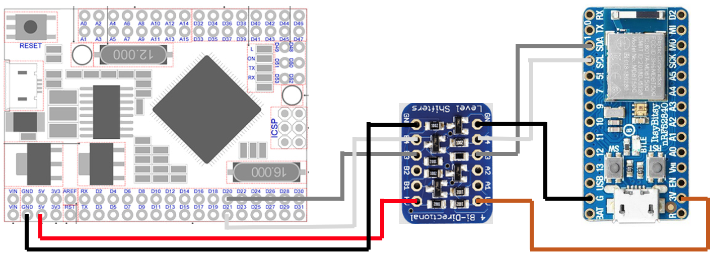
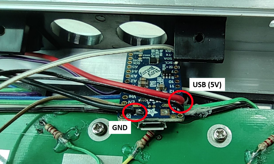
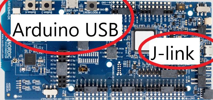
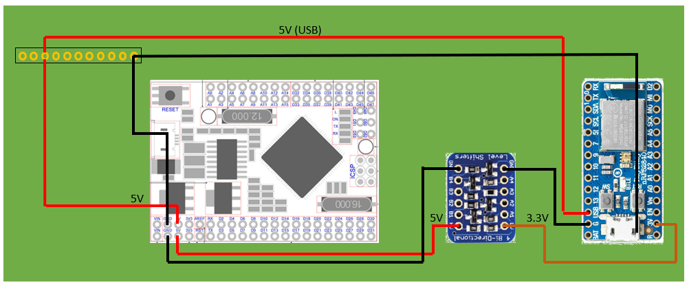 Although the "USB" pin (5V) on the itsybitsy is said to be an output only, I checked the schematics and it can also be used as an input to power the Itsybitsy board. this means whenever the ATmega2560 Arduino needs to be programmed, it should be OK to just leave that board connected to USB, and the Itsybitsy will then be powered from the Atmega2560 Arduino 5V output through its "USB" pin.


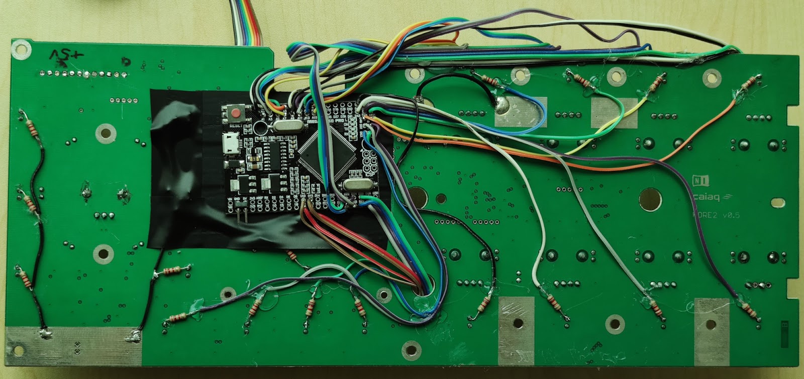
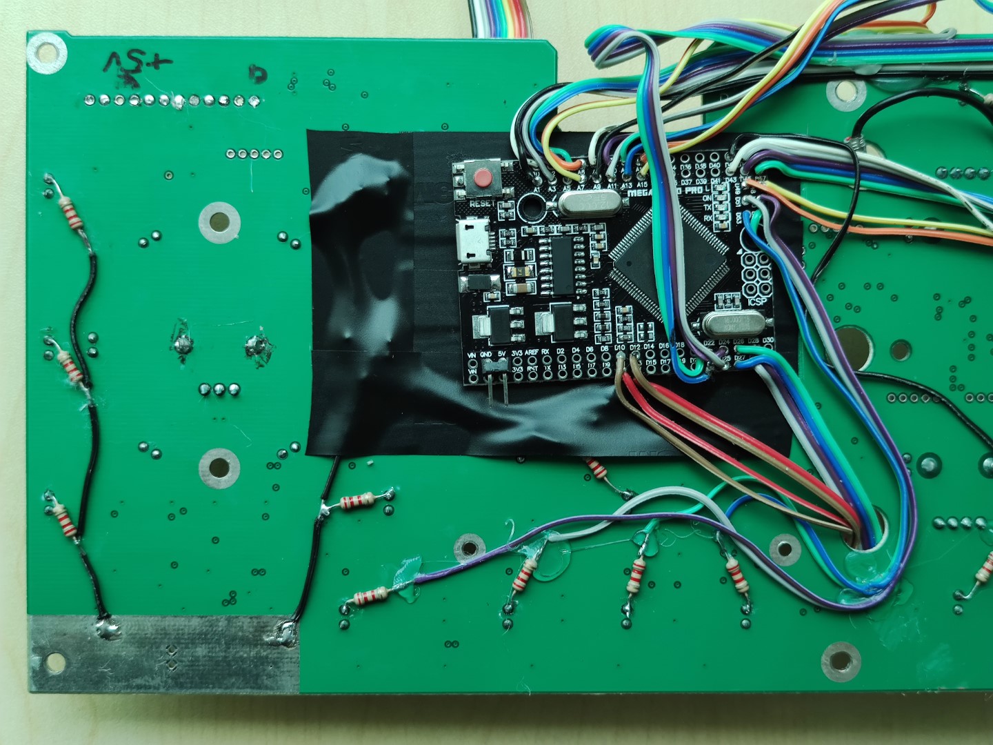
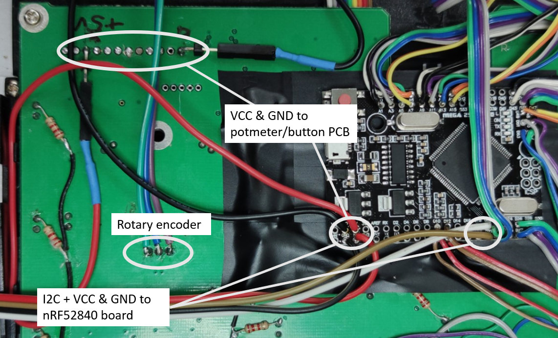

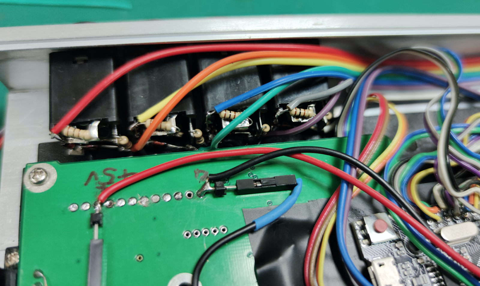
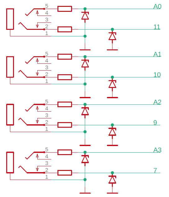
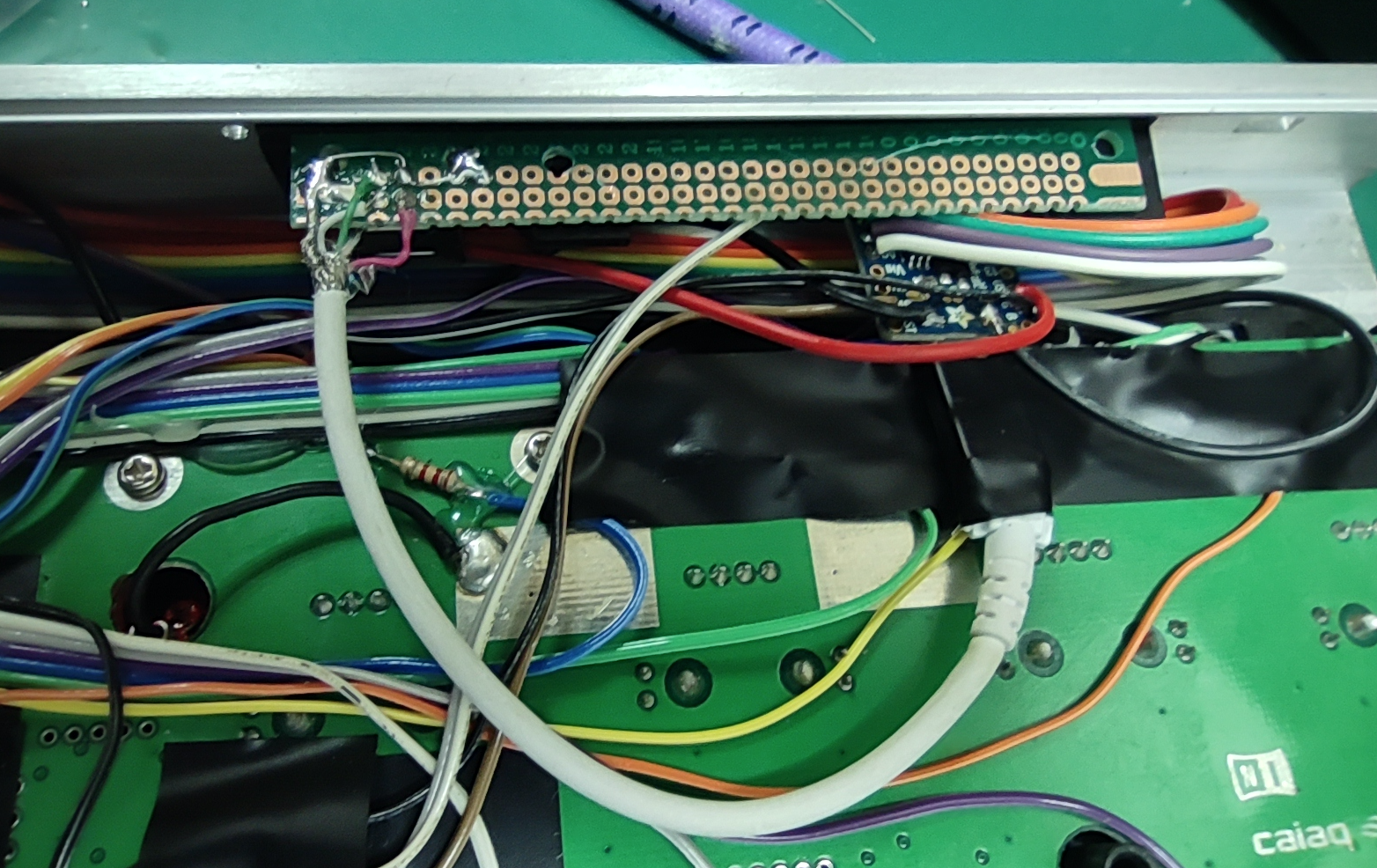
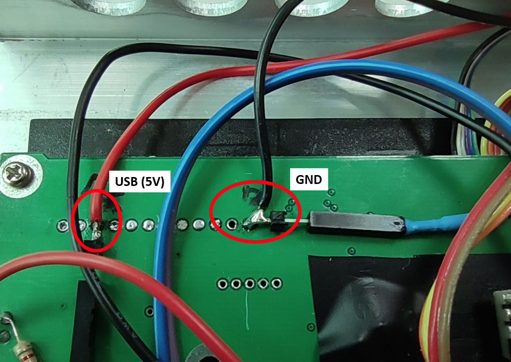
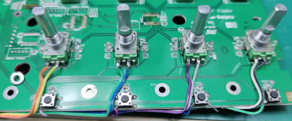
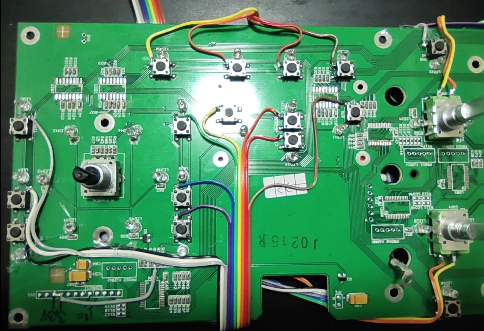
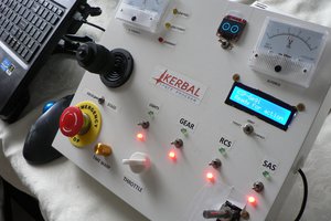
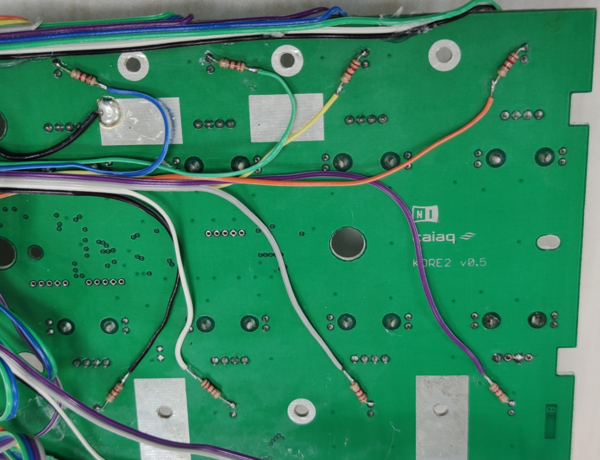 Wiring for the playback control button LEDs to be connected to the Arduino (the 4 resistors at the bottom), and the LEDS for the control and navigation buttons connected via the resistors directly to GND to stay constant on. The black insulation tape is the area where the mega2560 Arduino will be placed.
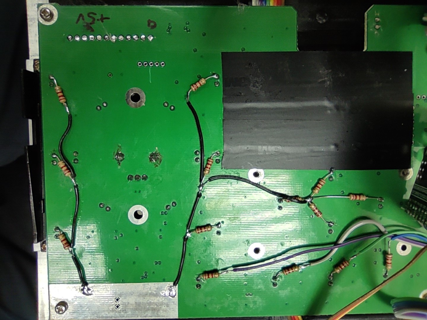
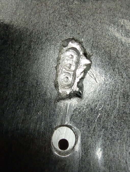
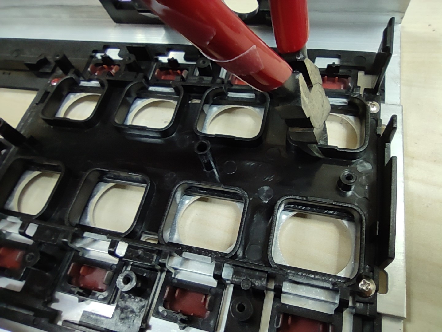
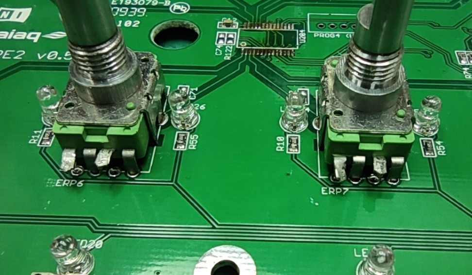
 Finish off by removing all the residue solder with a solder wick.
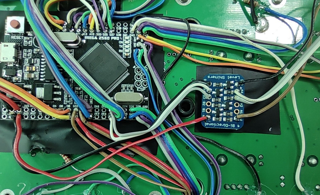
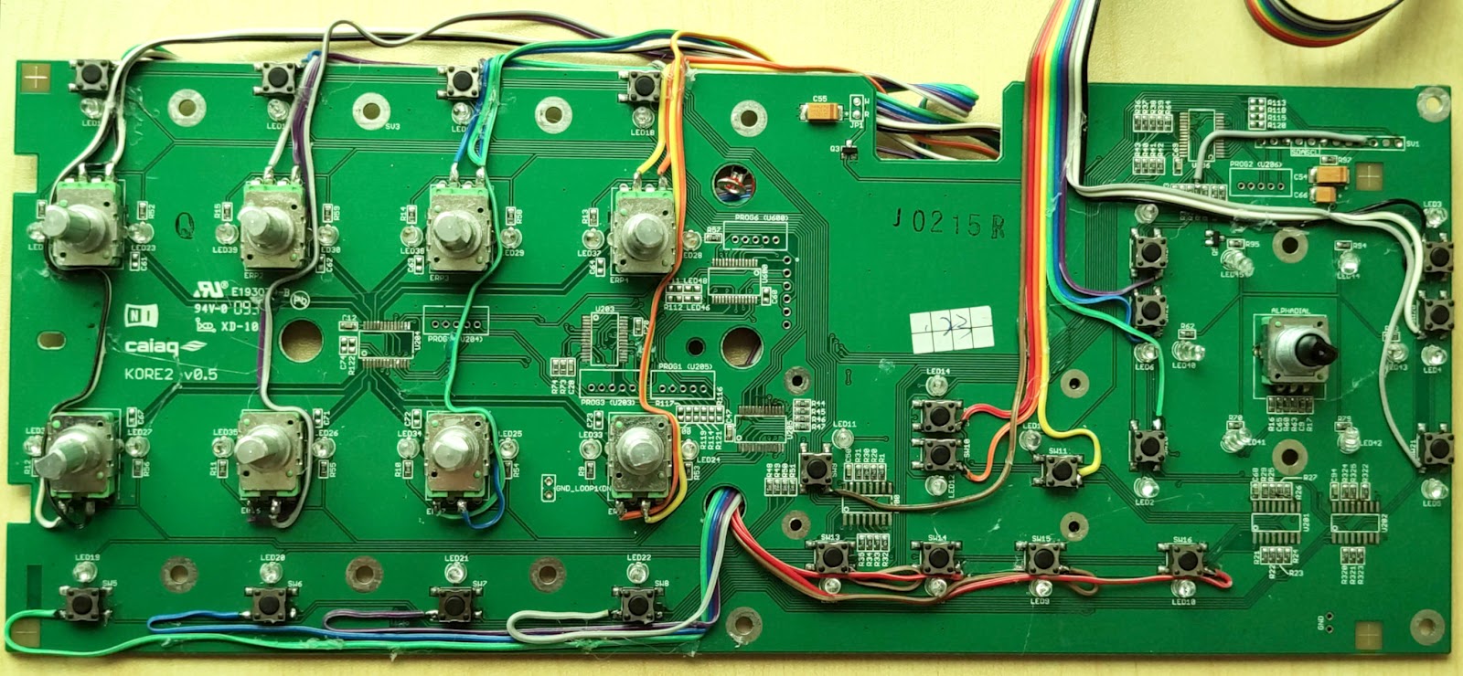
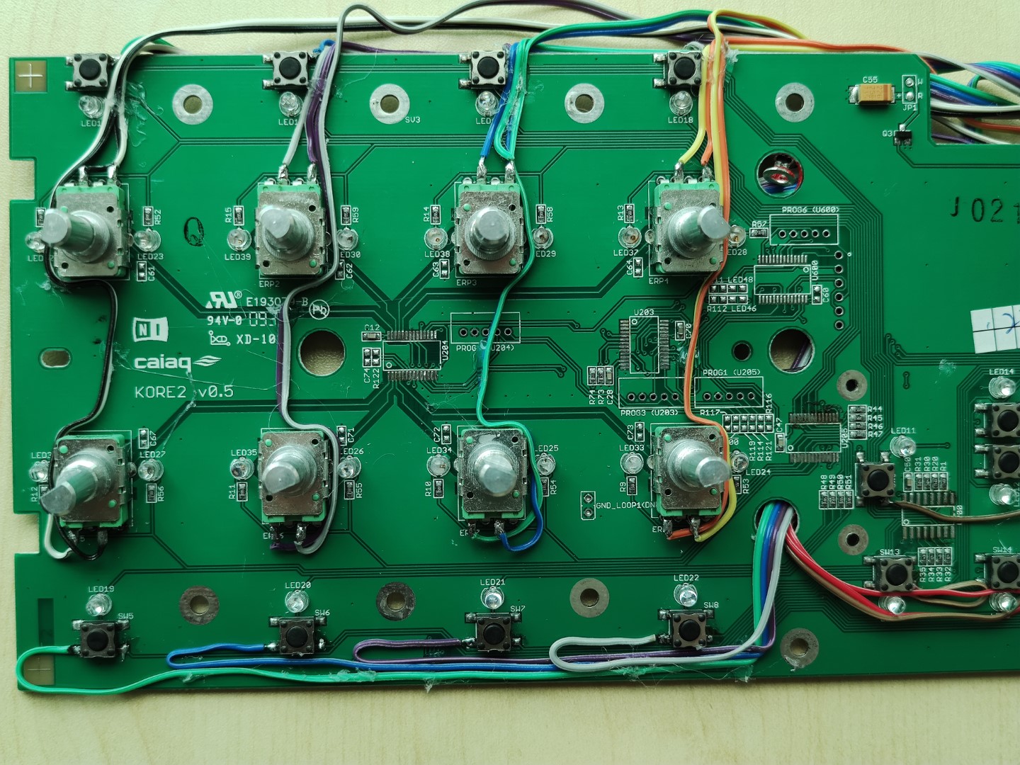
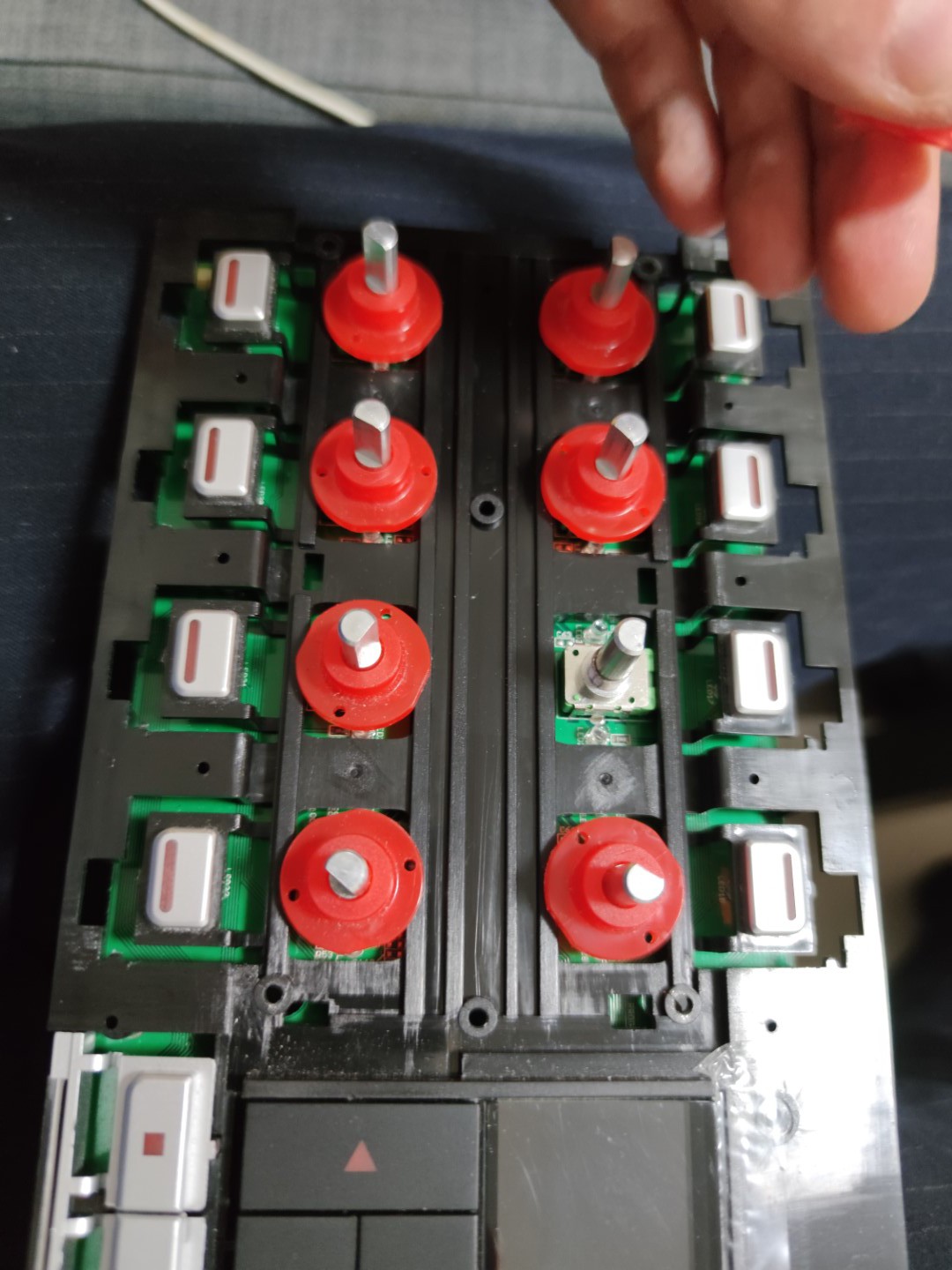
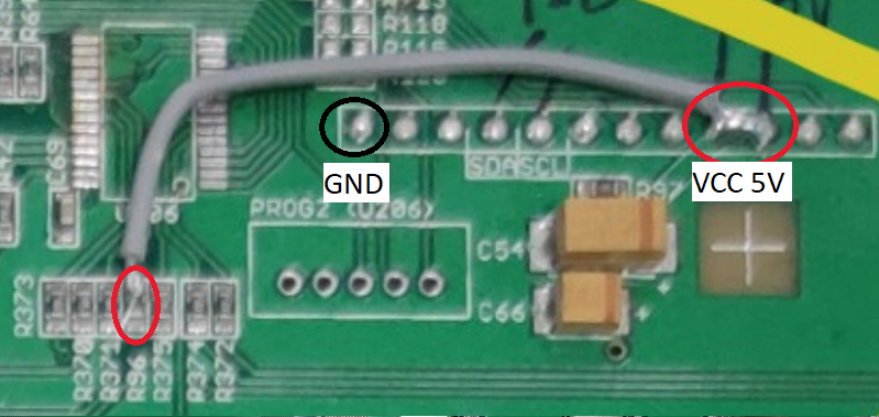
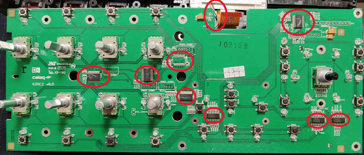 Use a pair of sharp wire cutters and cut pin 1 and 3 of each of the potentiometers, and bend the pins outwards, and solder wires to the pins, long enough to reach around to the back-side where the Arduino will be mounted.
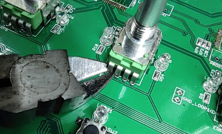
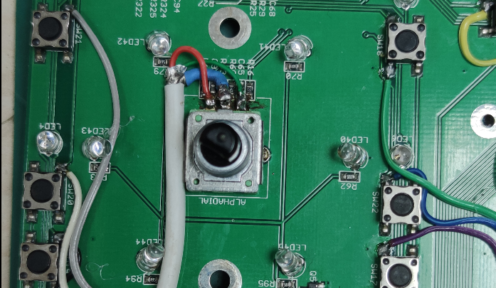
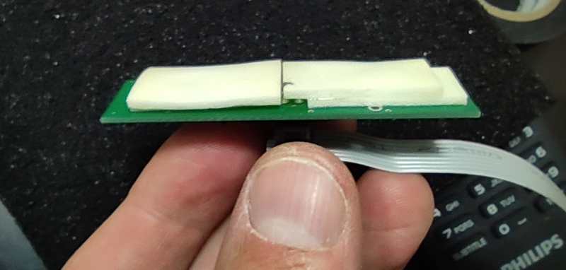
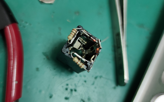
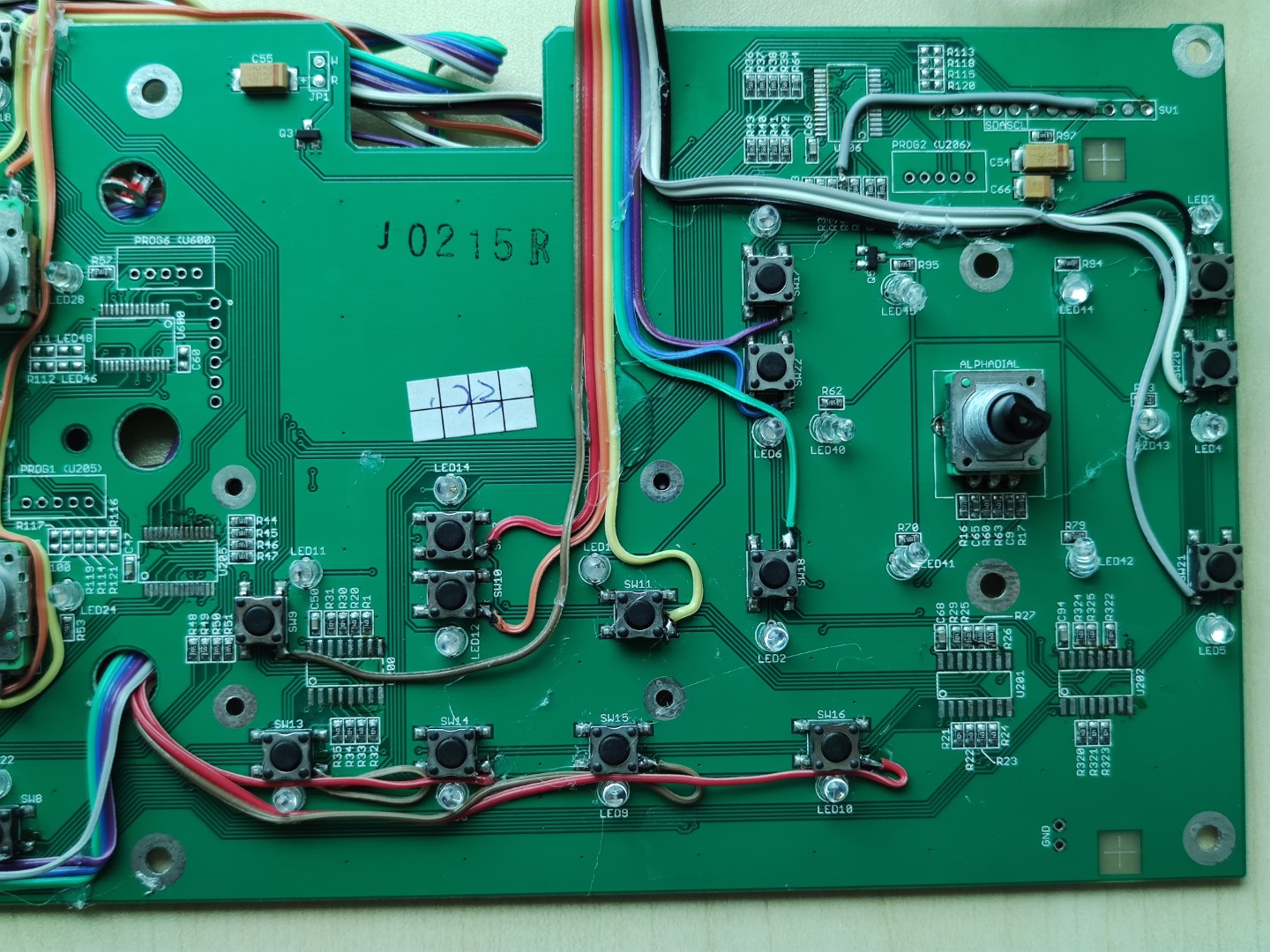
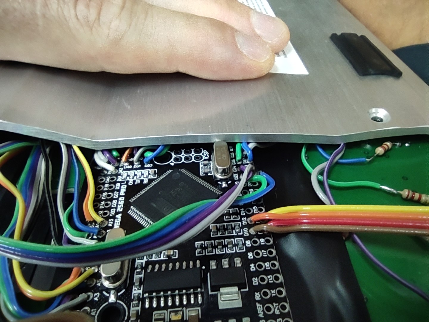
 Next, solder wires to the 8 buttons. These buttons are active high, and pulled low by resistors when not activated. Picture below shows which button pin to attach the wire to. If you are unsure, use a multimeter and check with pin goes high when button is pushed
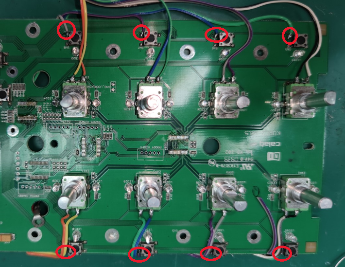
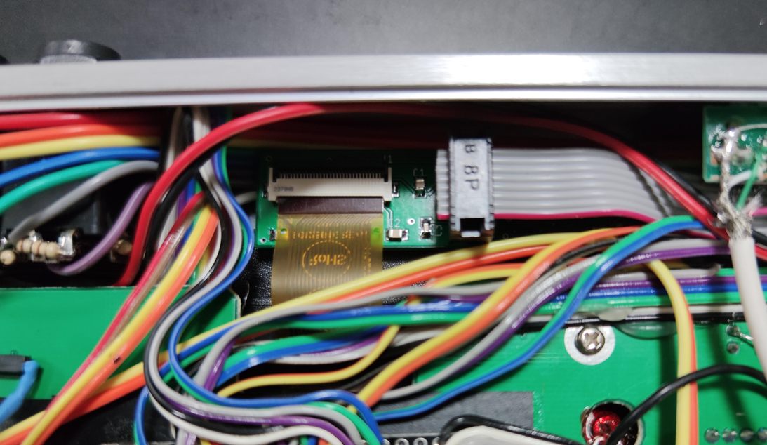
 Open MIDI BLE Connect and click on the Bluetooth scan button.
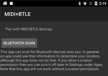


 5Volt-Junkie
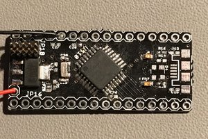
 Maciej Witkowiak
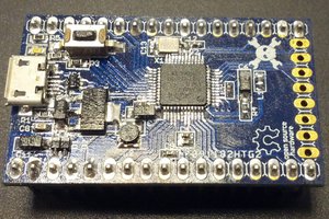
 Michele Perla
Hello friends, I just registered, I have a KORE 1 interface, and to say that both the audio and the midi are recognized by W10... but I am trying with OSX MOJAVE... it is true that it does not recognize anything if you install its latest drivers, but if you install AUDIO 8, it recognizes the midi part and appears in the audio section, but no sound comes out, it doesn't work! Does anyone know if it is possible or is there a way for the sound to work with osx mojave kore 1????