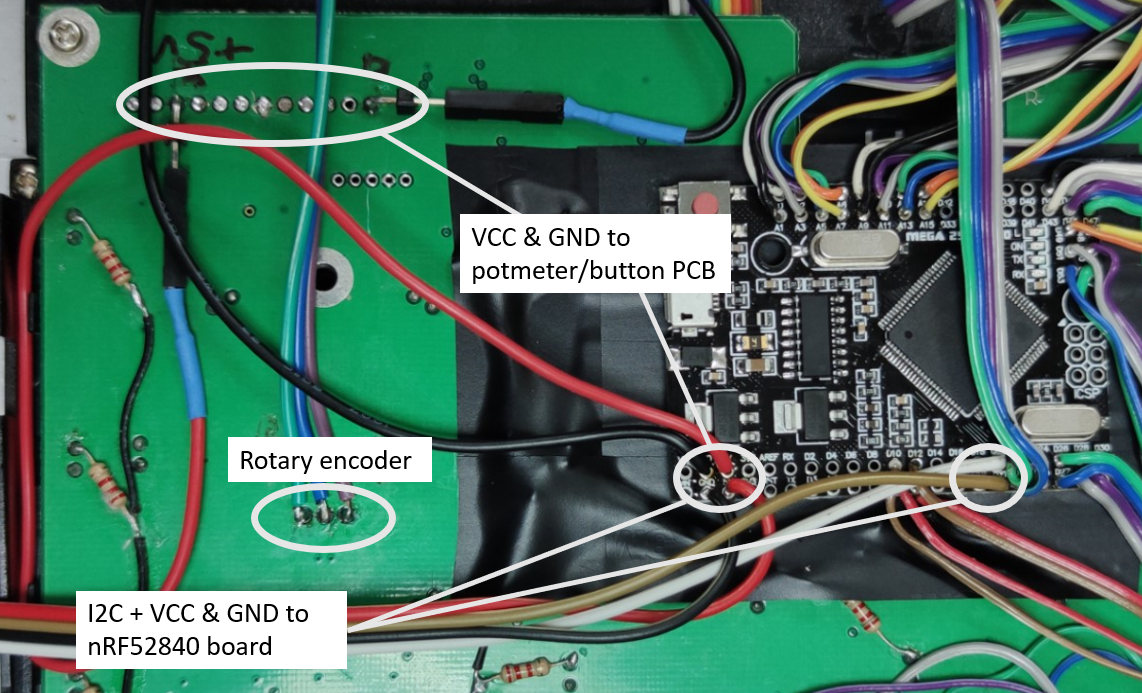
With all the buttons, pots and LEDs wired it was time to connect it all to the Mega 2650 Pro EmbedArduino board.
As earlier mentioned I plan to use two Arduinos, one ATmega2560 based and one Adafruit feather nRF52840 Express. I made the following sketch to show how the different parts will be partitioned between the two arduinos.
UPDATE: I later found that a different partitioning was better where the ATmega2560 reads all buttons and knobs except the rotary encoder. See later update.

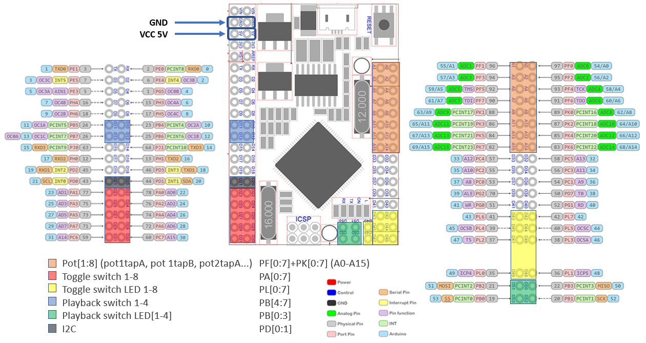
The following diagram (also available under files section) shows where the different buttons and pots should be connected to the Mega 2650 Pro Embed Arduino.
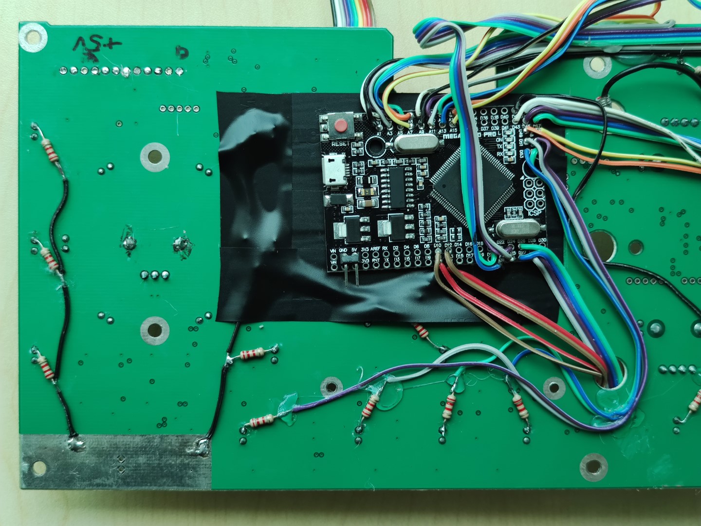
With so many pots and buttons connected with cables, the connections are deemed to get a bit messy. Also the space in the KORE encapsulation is really tight, and the only viable place I found for the Arduino is on the backside, opposite side of the PCB as compared to the LCD display. It is actually a bit too tight, and with the backside cover in place the Arduino will be forcefully pressed against the PCB.
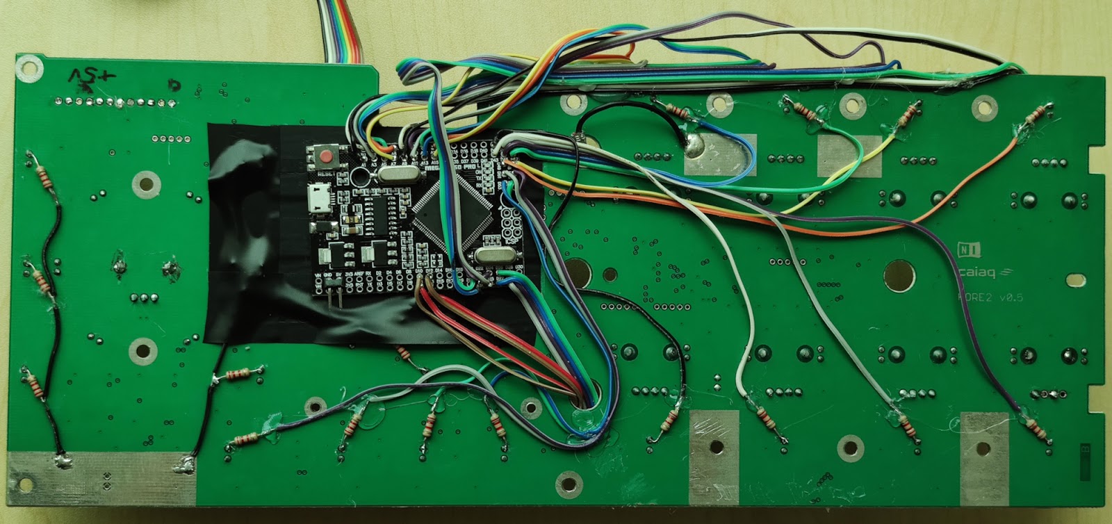
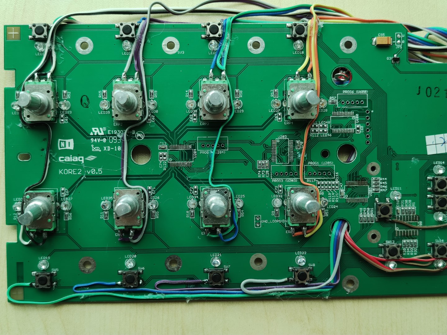
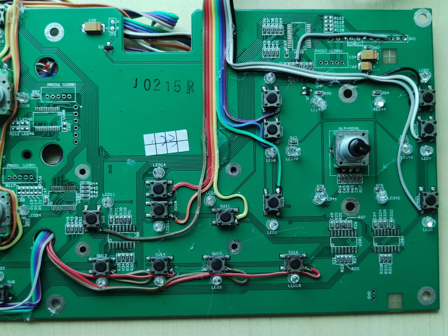
Notice that my original wiring with wires crossing over the PCB edge at the bottom had to be re-done as there is not room inside the encapsulation to have any wires going over the bottom edge. Luckily there is a hole in the PCB which can be used to pull wiring through.
This is how the new wiring looks from the top side:
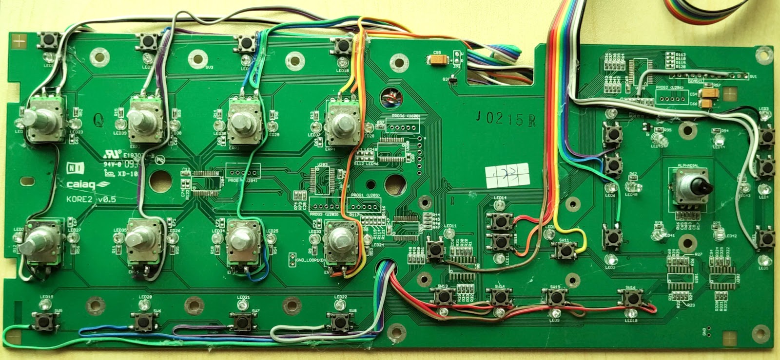
I also added power and I2C wiring, and soldered wires to the Rotary encoder.
To be able to reassemble the plastic frame on top of the PCB some openings must be cut to accommodate the wiring.
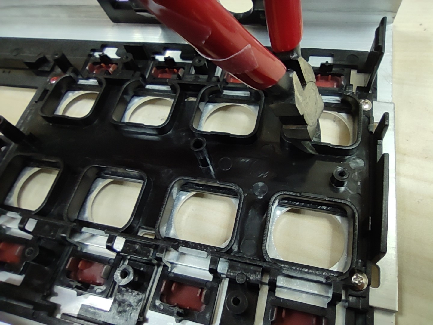
Several openings had to be made and will depend a bit on your actual wiring. So make sure that as you attach the wiring you also check with the plastic frame to make sure there are as few conflicts as possible, and then make cut-outs as needed.
As already mentioned the space inside the encapsulation is very tight, and the Arduino will be pressed hard down towards the PCB. So you have to make sure that anything soldered to the Arduino does not stick out on the back side to keep profile as low as possible, and also avoid anything digging through the insulation tape and shorting to the pot/button PCB.
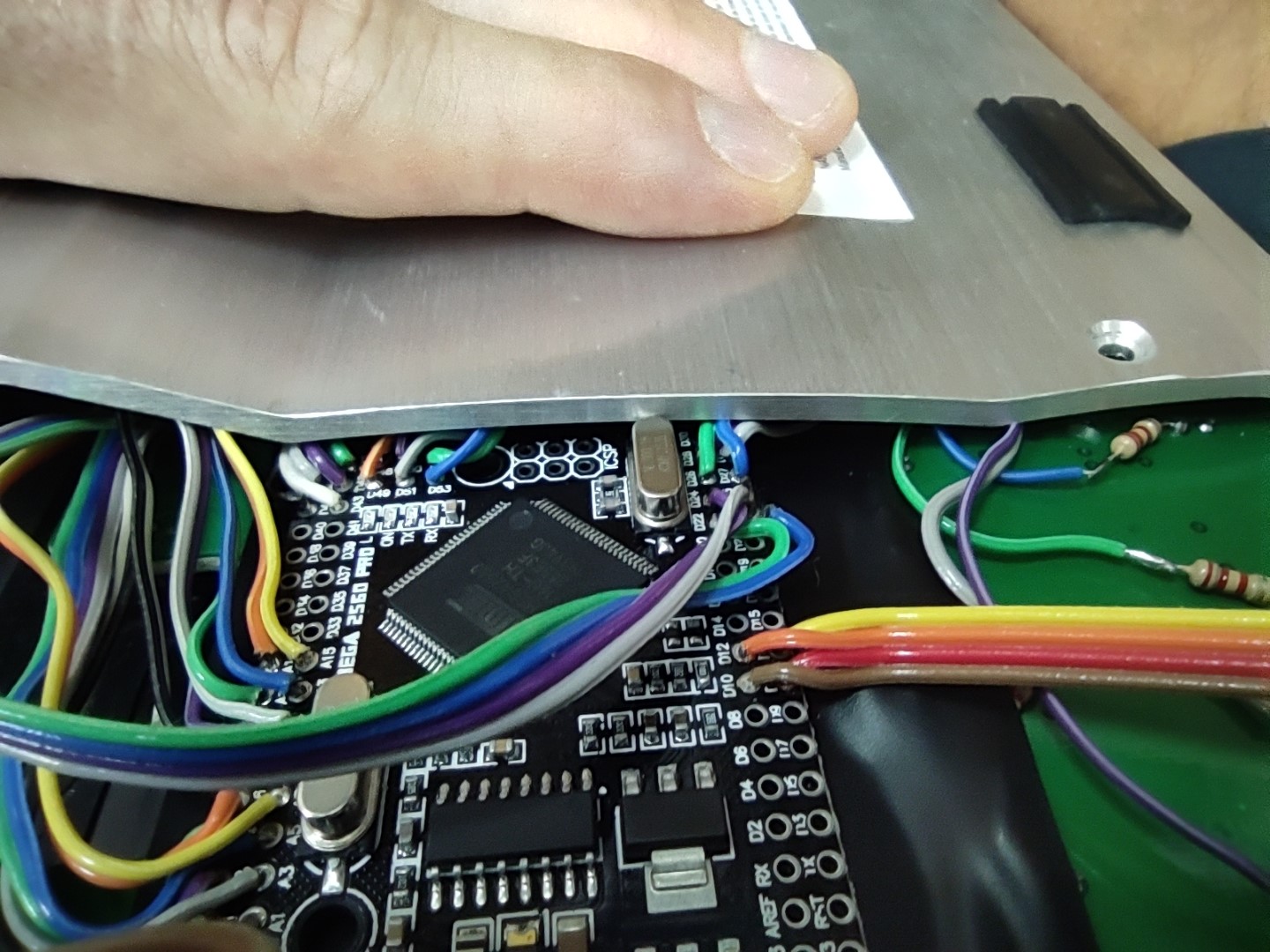

Current plan is to just screw the back cover on as it is. But I might potentially have to bend it a bit to make some more room for the Arduino. Or possibly 3D print some plastic to fill the gap.
Discussions
Become a Hackaday.io Member
Create an account to leave a comment. Already have an account? Log In.