Taylor Schweizer
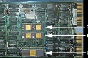
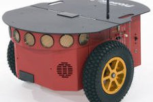
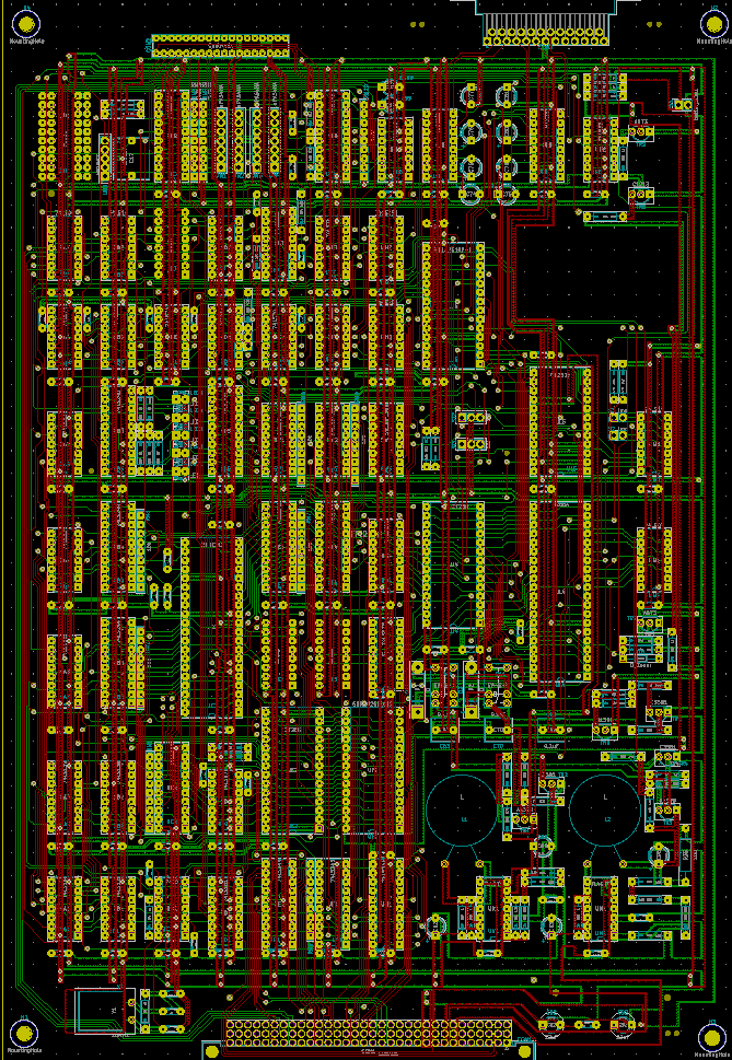
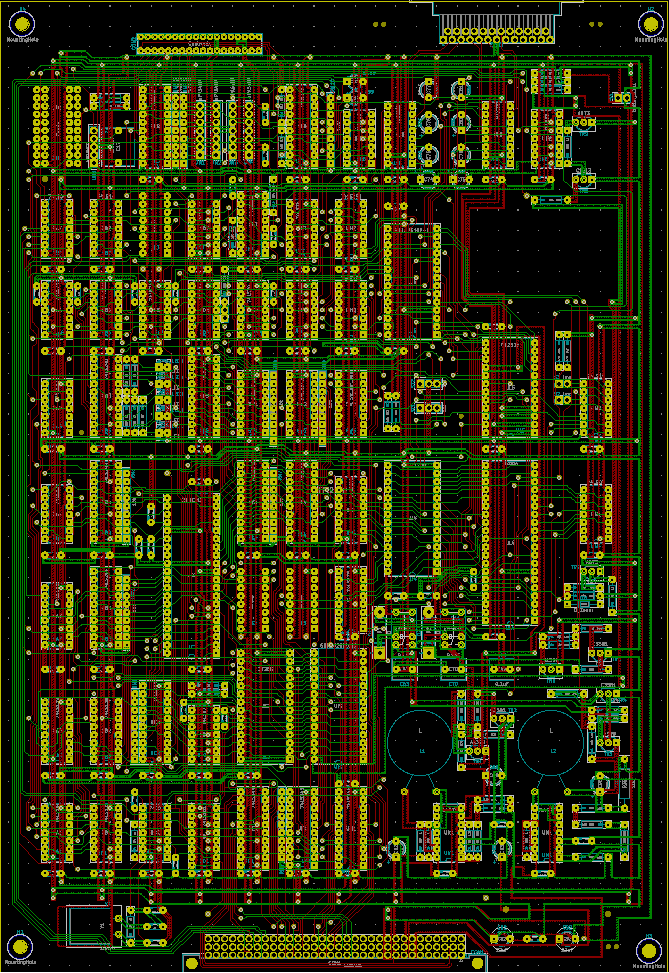
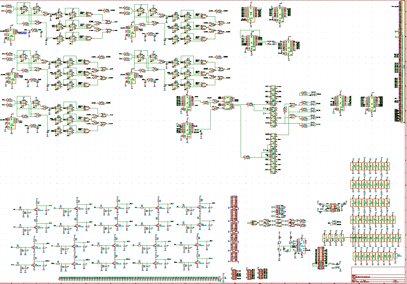
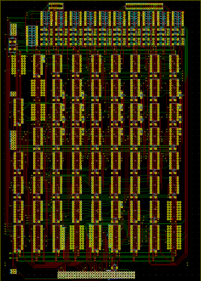
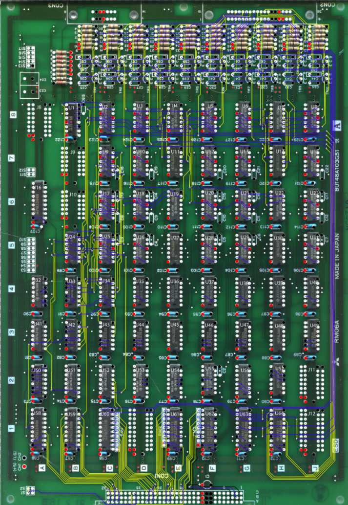
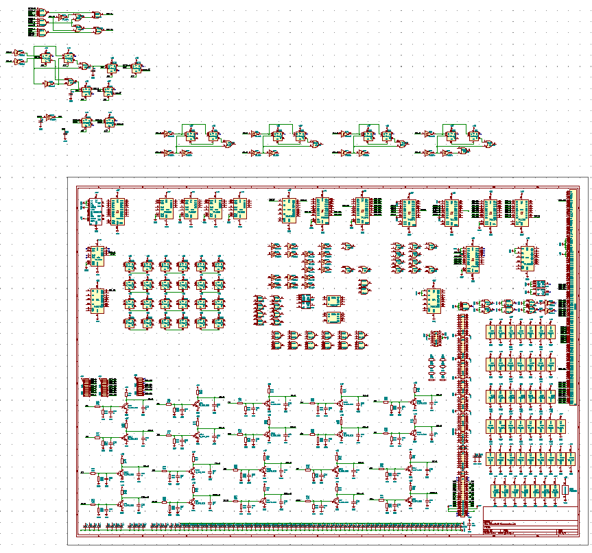
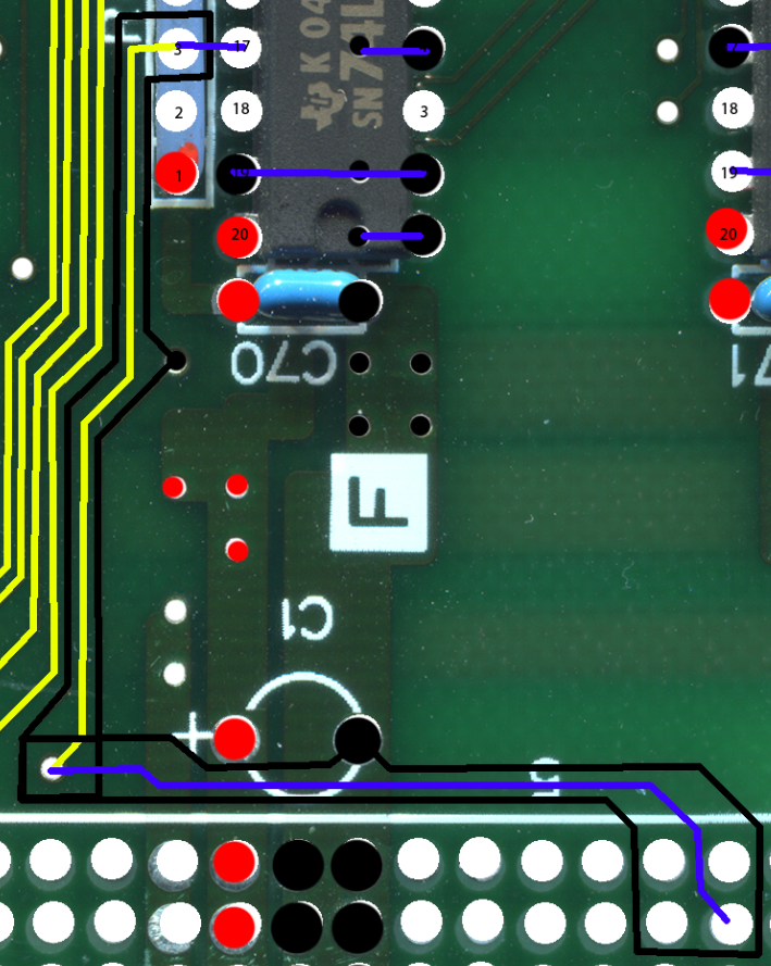
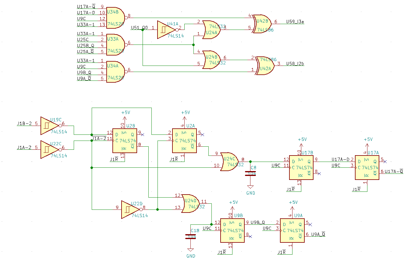
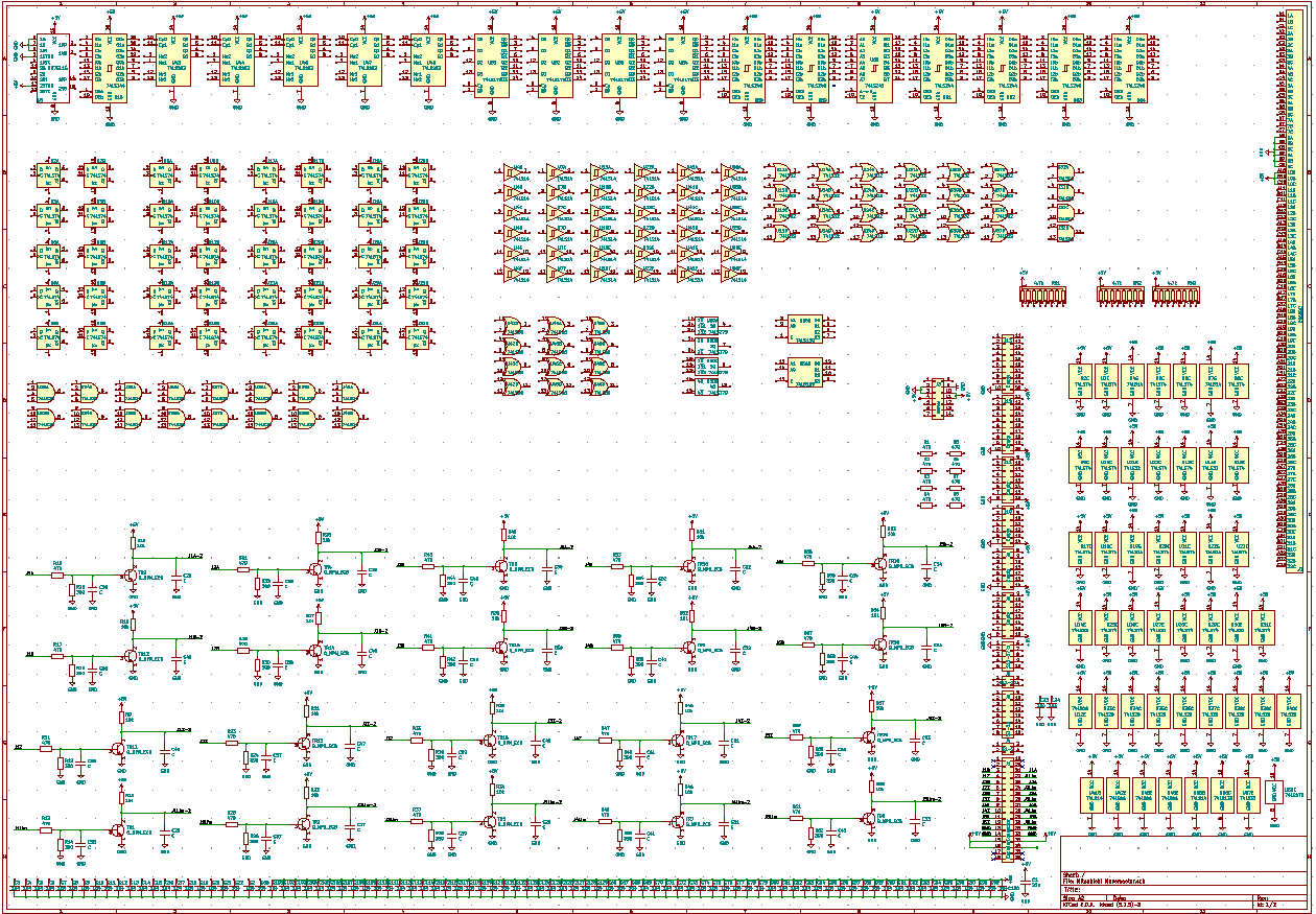
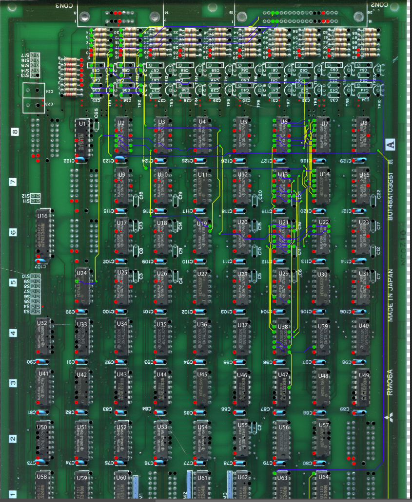
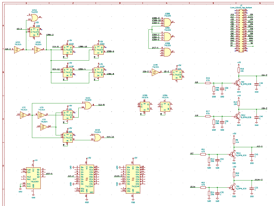
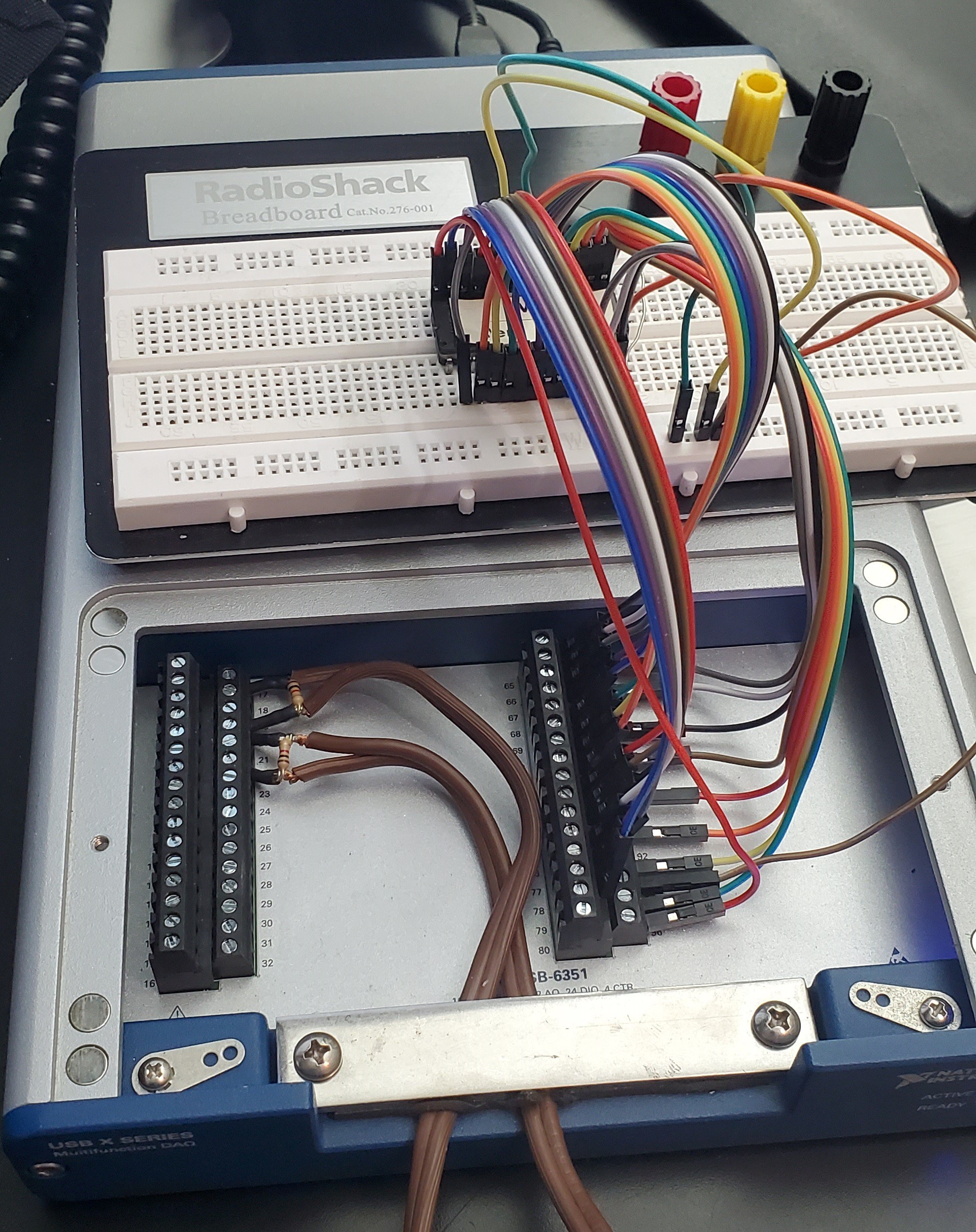
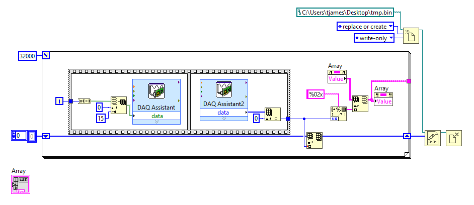
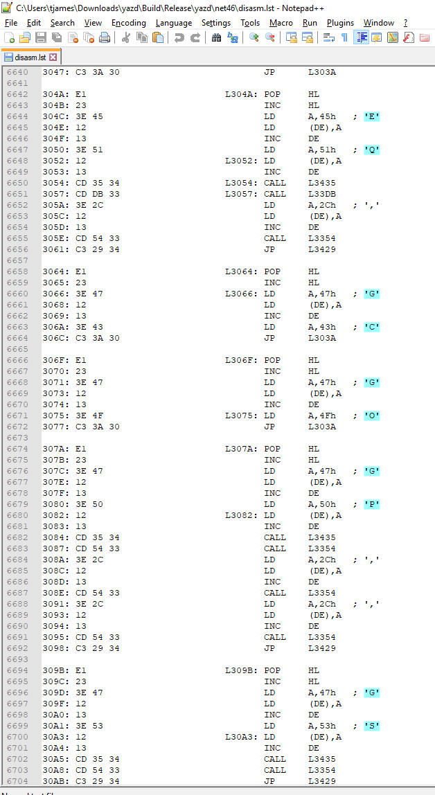
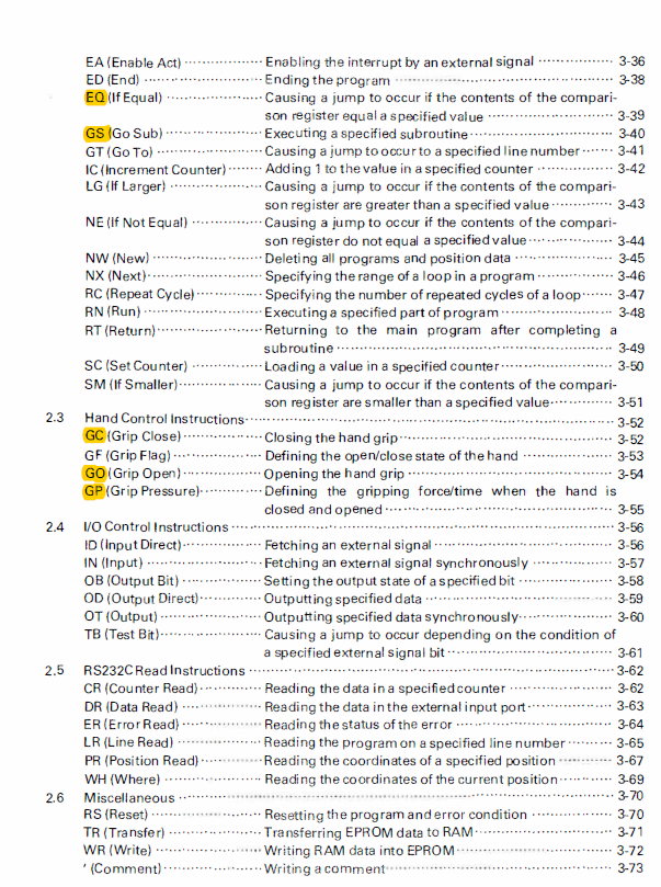
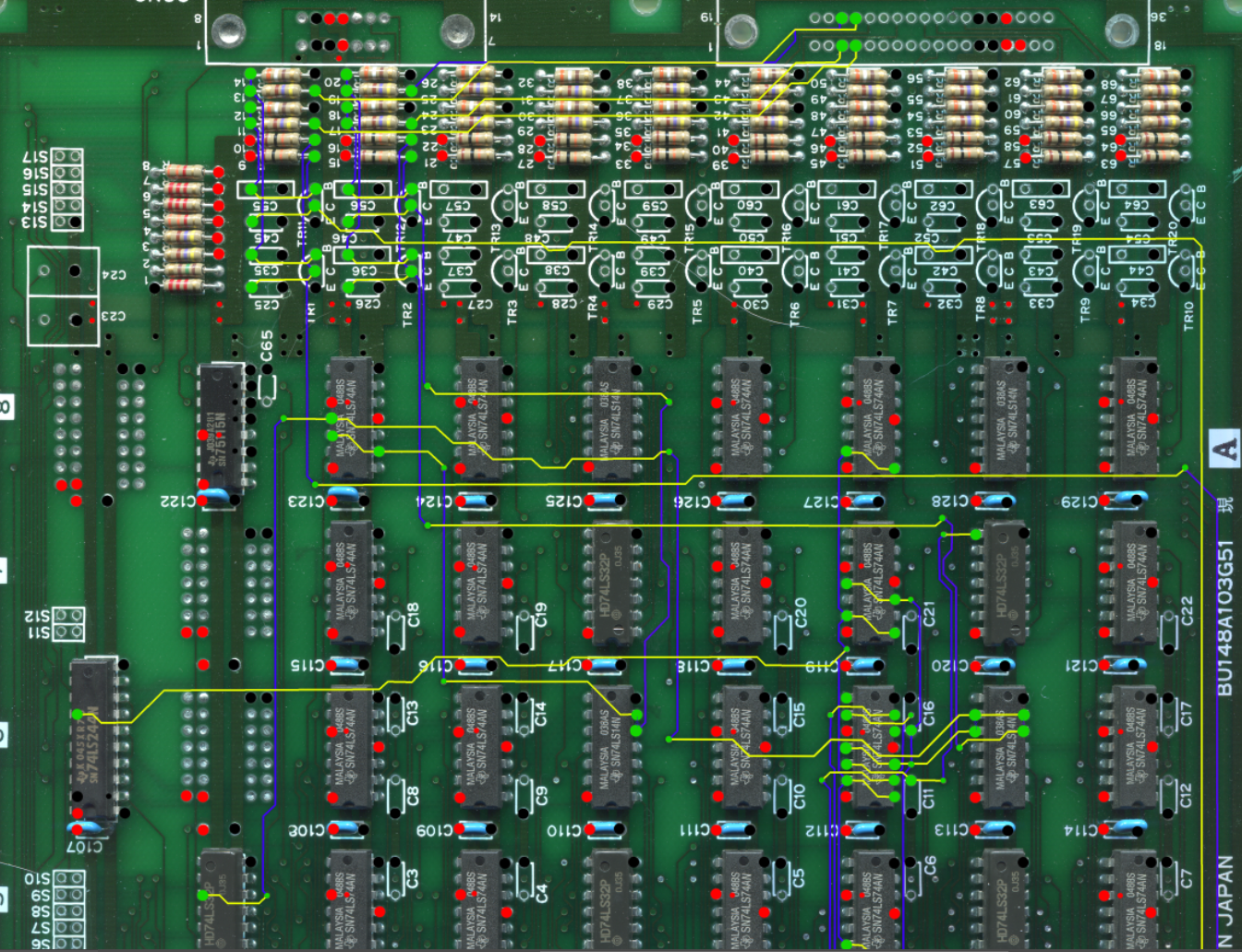
This will be a two part project. First, I'm going to do some reverse engineering of the drive unit because I'm curious how they implemented some aspects of the kinematics. Second, I'm going to make a controller to replace the drive unit.
0%
0%
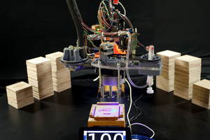
Reviving and Reverse Engineering an Old Robot Arm
A full reverse engineering and rebuild of a Mitsubishi Movemaster robotic arm
Become a Hackaday.io member
Already have an account? Log in.
Just one more thing
To make the experience fit your profile, pick a username and tell us what interests you.
Pick an awesome username
hackaday.io/
Your profile's URL: hackaday.io/username. Max 25 alphanumeric characters.
Pick a few interests
Projects that share your interests
People that share your interests
 anfroholic
 Torbjörn Lindholm