 Taylor Schweizer
This is getting extremely complicated extremely fast. A few things I've noticed (is anyone even reading these logs?):
- It seems as though the encoder channels have an auto zero function, as well as possibly an error correction? Either error correction or some type of position-to-speed calculation.
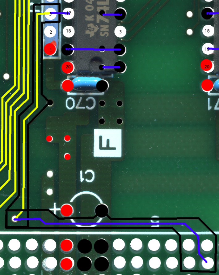
- There is a clock signal coming from the main board, and all of the traces are surrounded with a weird ground shielding trace. I'll post a picture below.
- I had to pull out the board that all of these large boards plug into to trace where the clock signal is coming from. Looks like they are using a binary counter to divide clock signals.
Here's my idea - I really, really want to make an identical board but with modern components. For instance, instead of using the 20 pin DIP packages for the SN74LS240N, I want to use the 20 pin SOIC package. Replace all transistors with a sot-23 package, resistors with 0805 SMD, etc. Basically I want a board with the exact same number of items on the BOM, but with all SMD parts. Just to see how small I can make the board. No idea if I'll actually do this or not, really seems like I'm writing this just for myself.
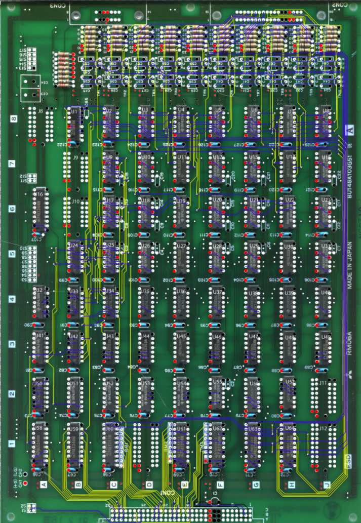
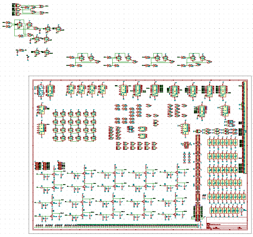
There will be a few pictures today, the usual zoomed out view as well as some specifics on both the layout and the schematic.
Here is the weird ground trace. Quick color convention - blue traces are on the bottom, yellow traces are on top, the black traces are ground traces. They surround the clock trace.
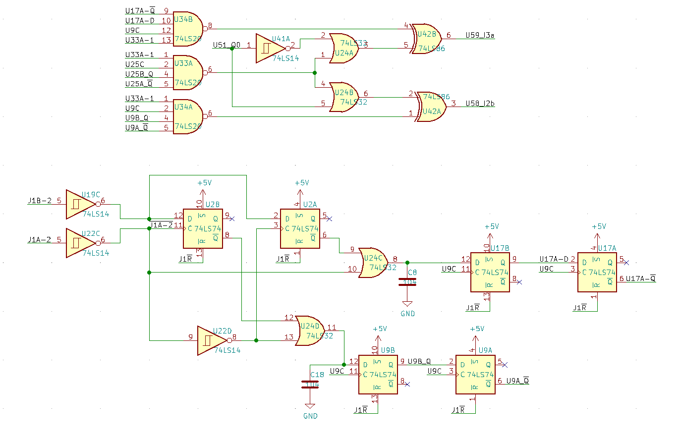
Here is most of the schematic for the encoder for joint 1. This is just one joint. There are 4 more. But just like the input conditioning, it seems to be duplicated.
Discussions
Become a Hackaday.io Member
Create an account to leave a comment. Already have an account? Log In.