 Taylor Schweizer
So I went ahead and simulated what I had so far for the joint 1 encoder circuit using Logisim Evolution. It looks like a simple converter between the quadrature output of the encoder to an up/down signal, and it uses the index signal and the limit switch as a reset. Take a look (ignore the clocks and stuff, I haven't quite figured out how they are connected - also the DirSelect on the left side of the screen is what I use to change the direction of the encoder i.e. whether A or B is leading or lagging):
Here's the chronogram:
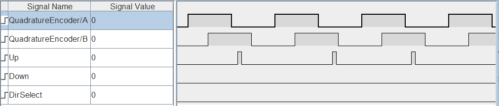
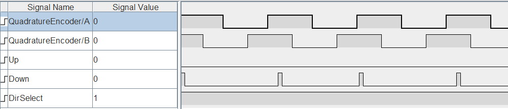
I'm still tracing back the stuff involving the Z index marker on the encoder, as well as the limit switch.
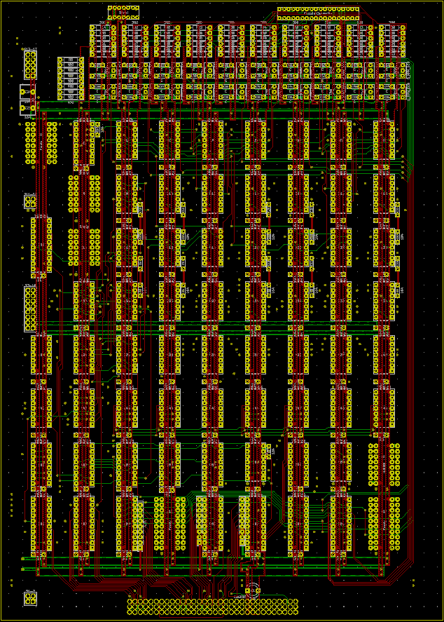
Here's the KiCAD PCB so far:
Discussions
Become a Hackaday.io Member
Create an account to leave a comment. Already have an account? Log In.