 Insight Machines Lab
The idea was quite simple. Buy a linear actuator from OpenBuilds with a stepper motor, attach a camera on top of it, two tripods below, assemble a control box with some Arduino-compatible, WiFi-enabled board and write an Android application that would allow us to set up the device hands-off. Simple.
The Mechanics
The actuator we chose for the slider was one of those:
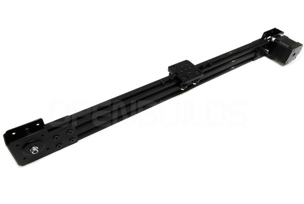
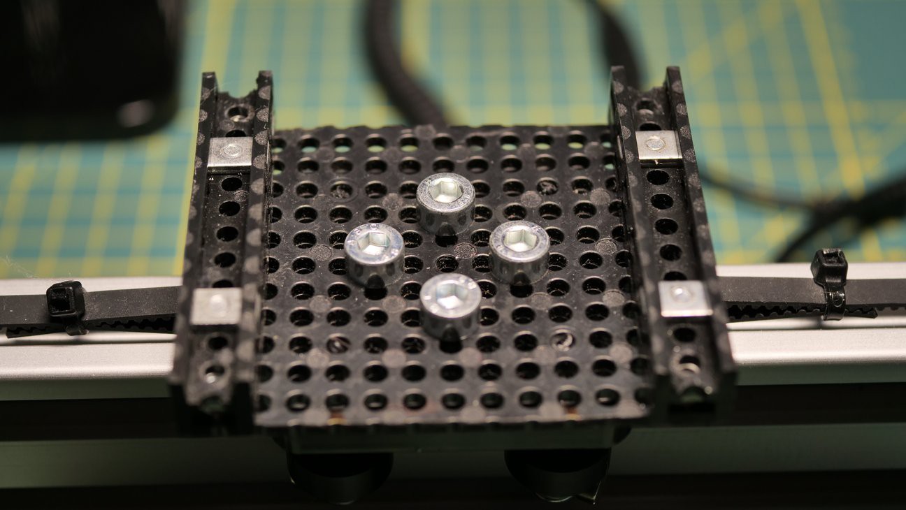
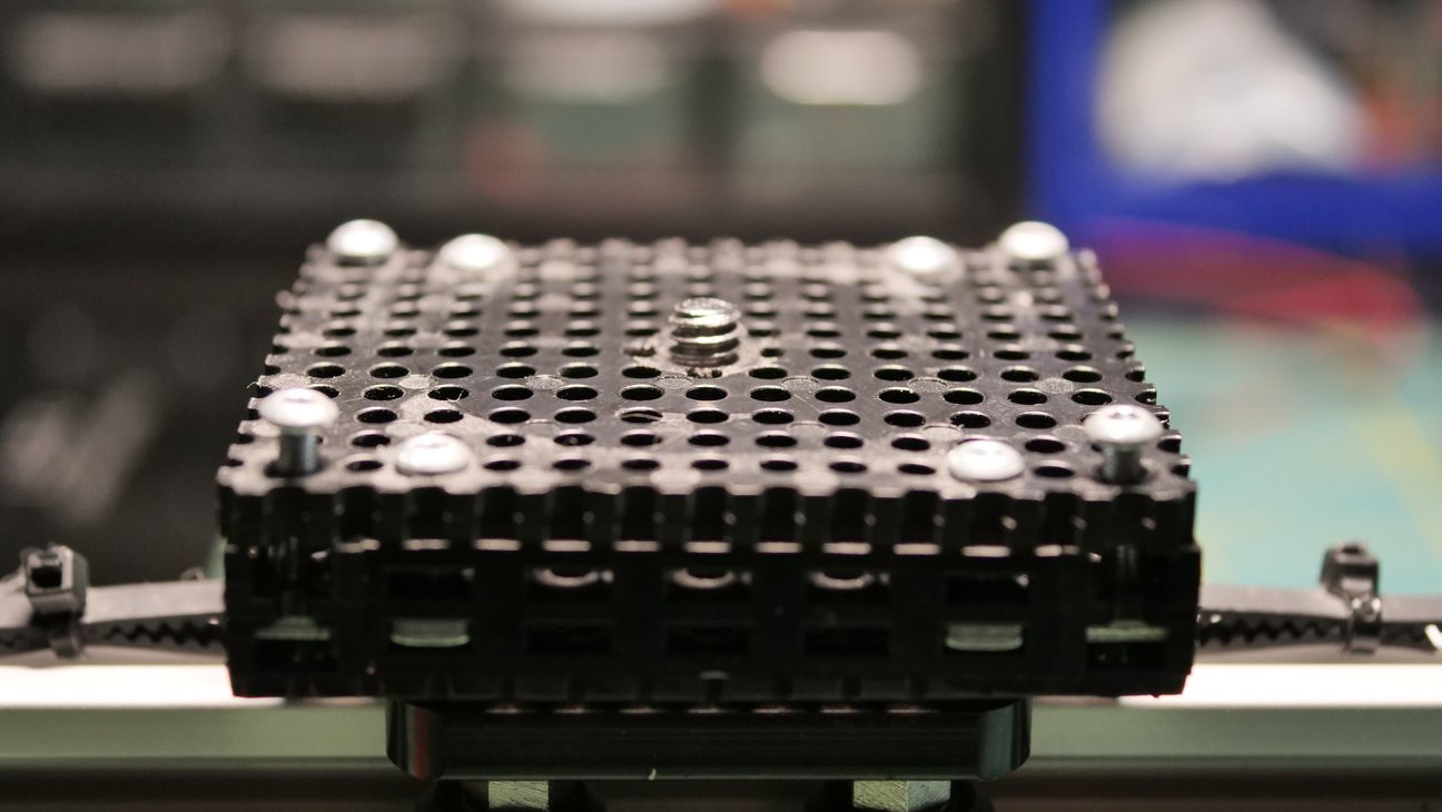
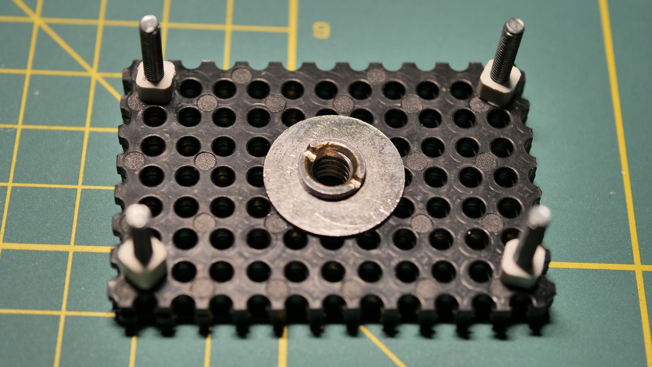
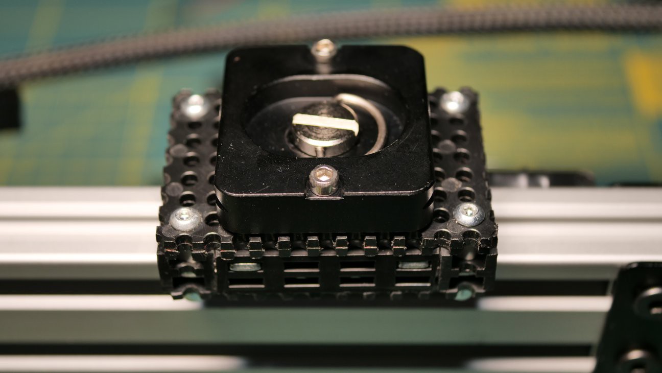
It's a V-Slot Mini V Linear Actuator from OpenBuilds. It is one meter long and has a NEMA 17 stepper motor on one end. The gantry plate is pulled by a timing belt and can be precisely positioned along the rail. That's perfect for a time-lapse slider. The problem was with mounting a camera on the plate. It does not have the standard screw (1/4" or 3/8") used in photography gear. Thus, we needed to make an adapter. That was accomplished with some plastic parts from Totem.
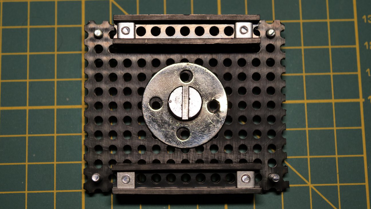
We used the same approach to mount quick-release plates to the bottom of the rail:
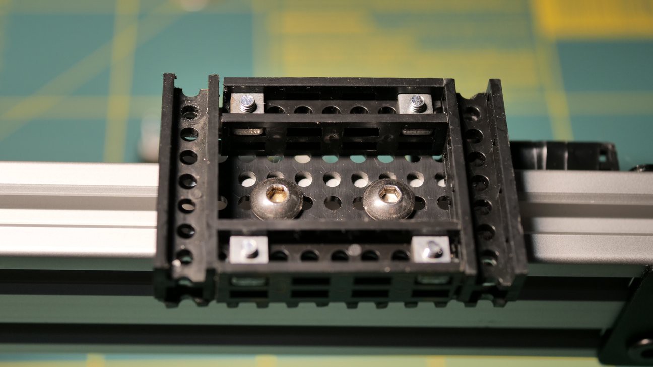
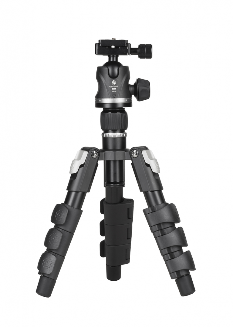
Those plates work nicely with any arca-swiss compatible tripods. In our case, we used two small but very stable tripods from Genesis Gear - the ABT Mini Kit:
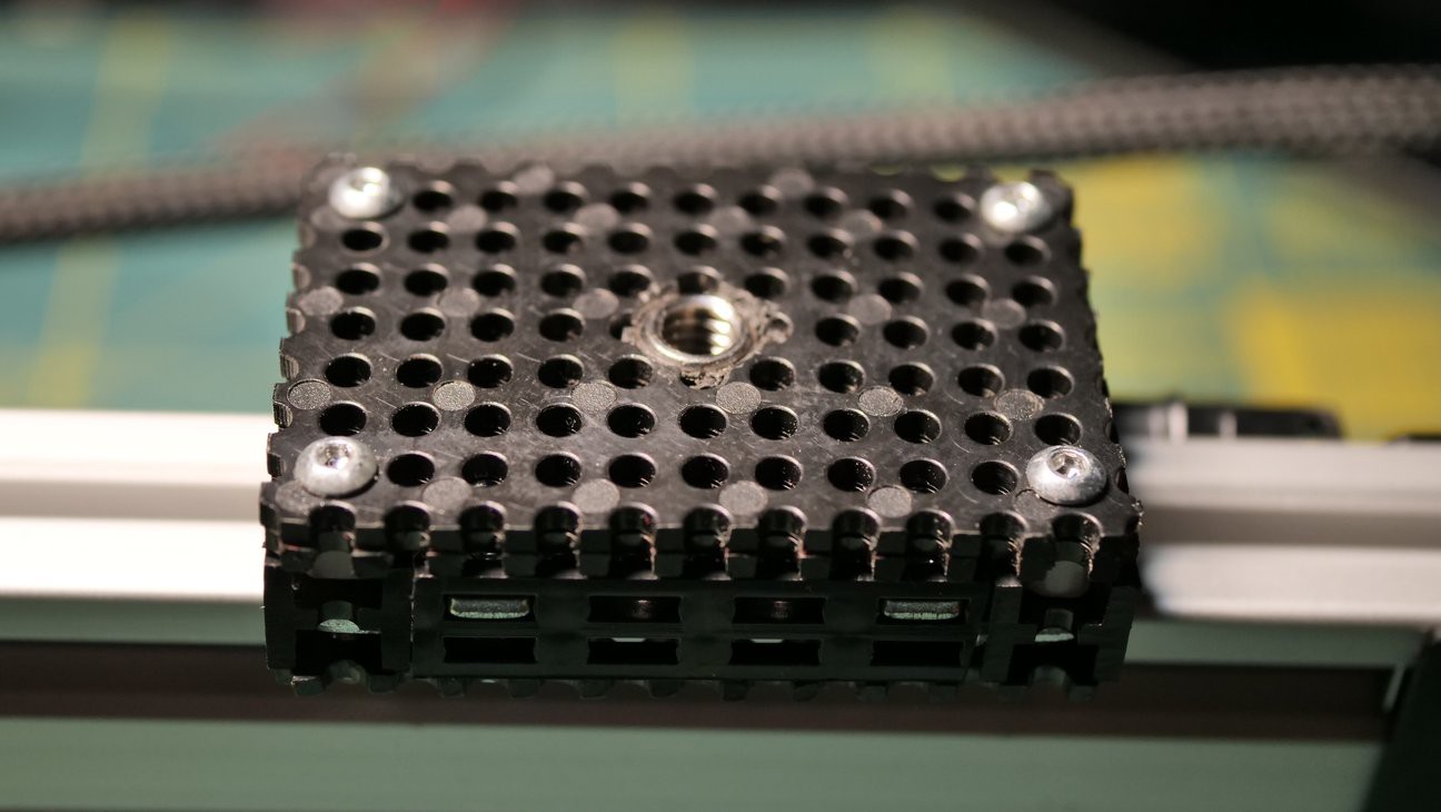
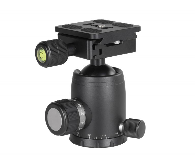
Since mounting a camera directly to the gantry plate would significantly reduce the ability to freely position the camera, we've mounted a ball-head. Again we went with a Genesis Gear product, the BH-34:
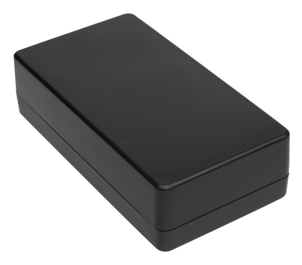
The control box needed a simple yet durable enclosure. One that could be easily opened and that we could modify a bit by making openings for cables and a power button. We went with a Kradex Z78.
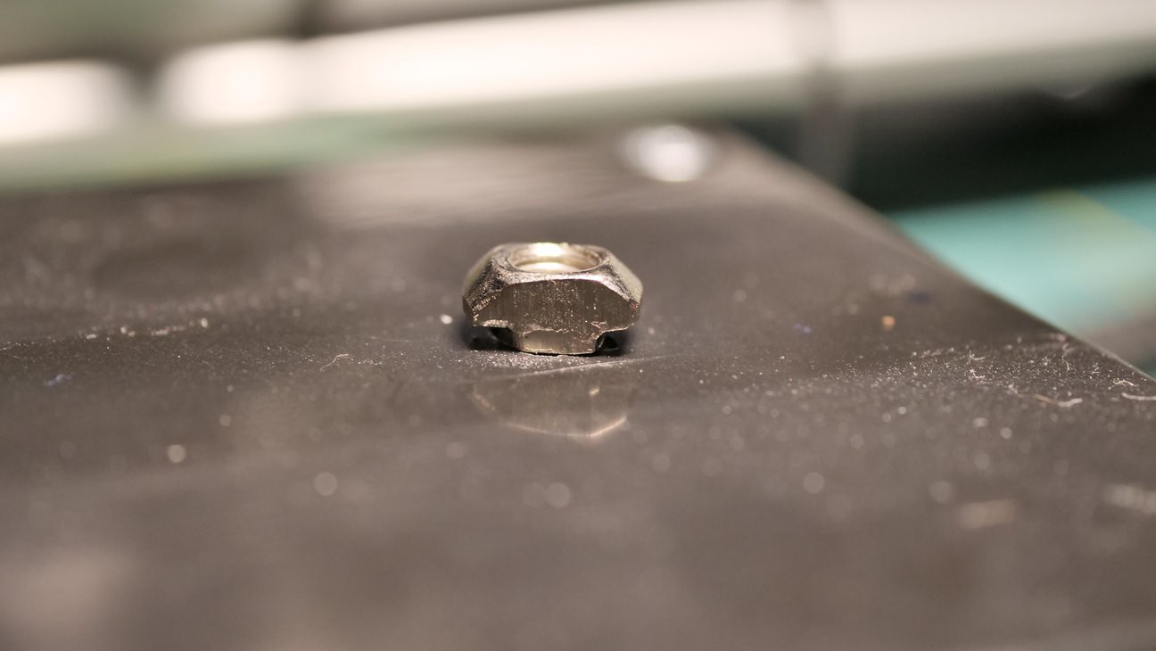
We mounted the control box to the rail with a couple of t-nuts that fit into the rails' groves perfectly: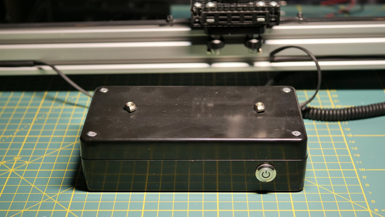
This is what the whole device looks like: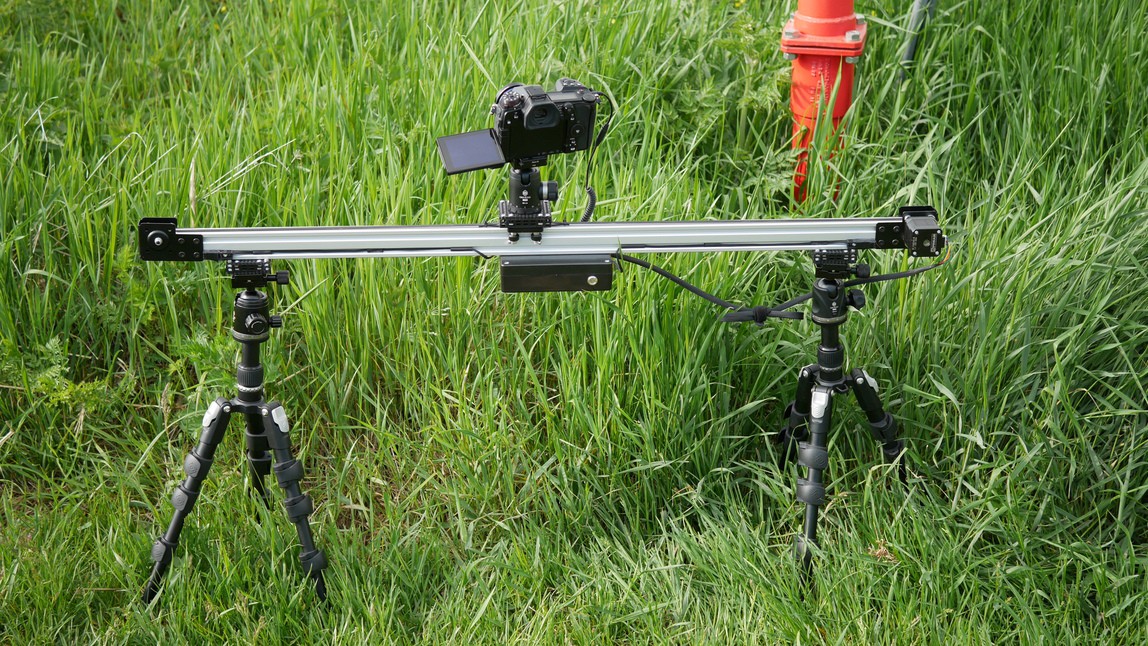
The Control Box
Inside the control box, we've packed four Lithium Ion batteries (18650), a Pololu A4988 stepper motor driver, an Adafruit Feather M0 WiFi with ATWINC1500 and a step-down 3.3V voltage regulator (under the batteries):
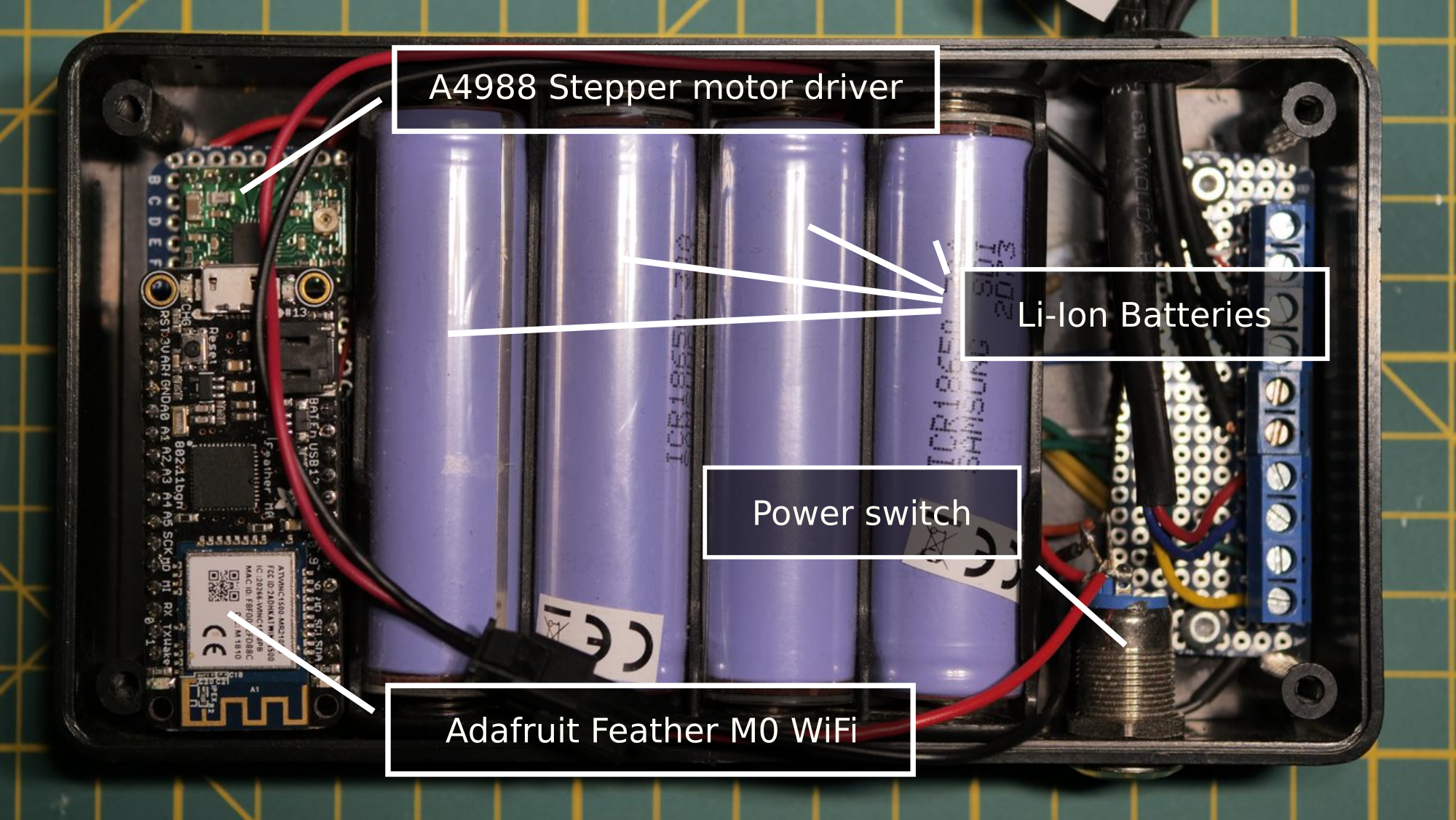
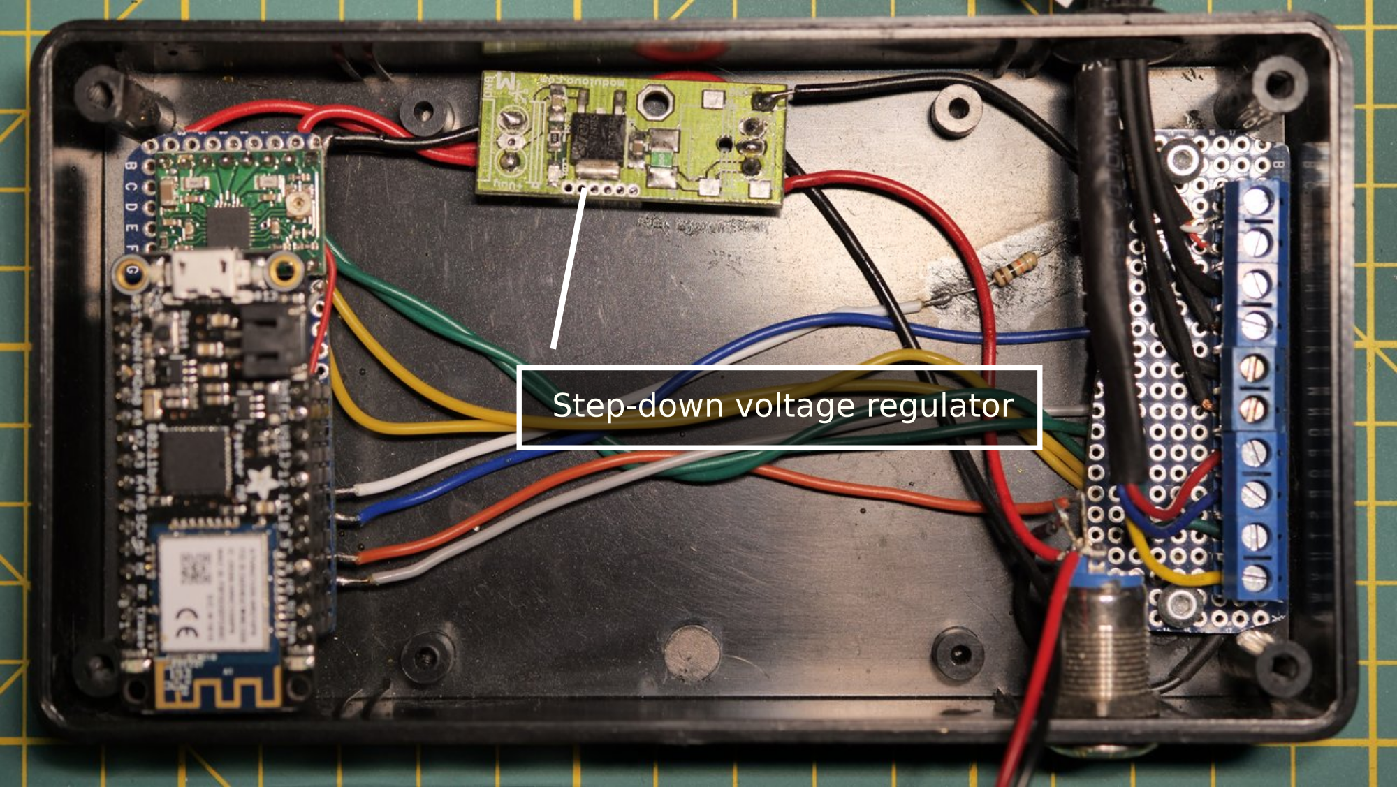
The batteries give us a nominal voltage of 14.8V which is enough to drive the stepper motor and way more than what the logic modules can handle. Thus, we've installed a step-down voltage regulator that reduces the voltage to 3.3V.
Motion Bounds
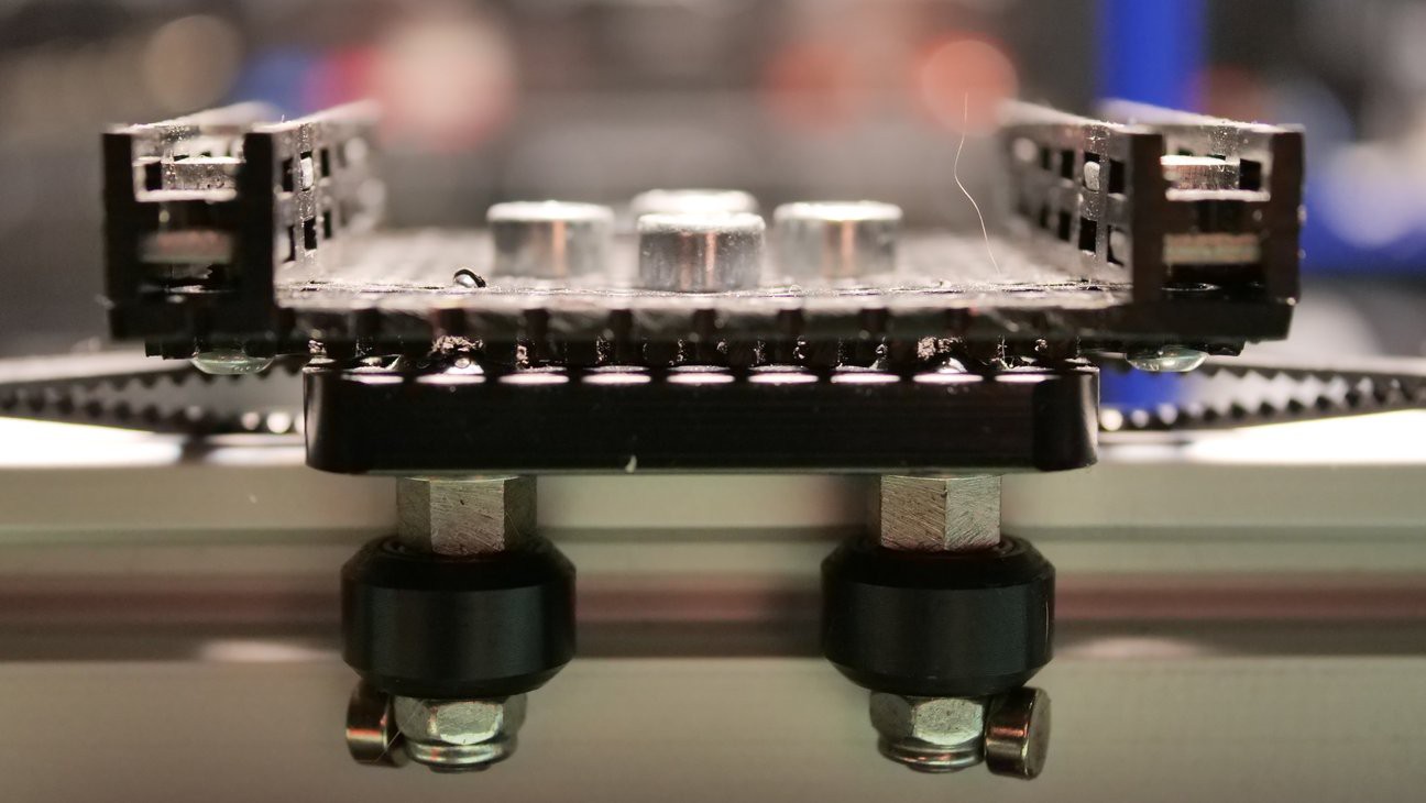
Although the stepper motor gives us precise control over the movement of the trolley, it does not give us any information about its current position. To solve that problem, we've installed reed switches on both ends of the rail and magnets on the bottom of the trolley. When a magnet gets close enough to a reed switch, the switch closes. The micro-controller detects that and at that point it knows where the trolley is. From then on, it can calculate the trolley's position simply by counting steps of the motor and keeping track of their direction. Although the reed switch approach is not very precise, it proved precise enough and reliable enough for our needs. The video below shows motion bounds testing done on an early prototype of the slider:
Remote Configuration
A motorized slider is only useful if it can be easily configured. From the very beginning of this project we considered two options: mechanical controls on the device itself or remote operation via WiFi/Bluetooth. We opted for the latter approach as it seemed more flexible and actually easier to implement. We chose WiFi over Bluetooth mainly because of the WebThings...
Read more »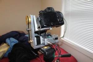
 Drew Pilcher
 Nicholas
 Ulrich