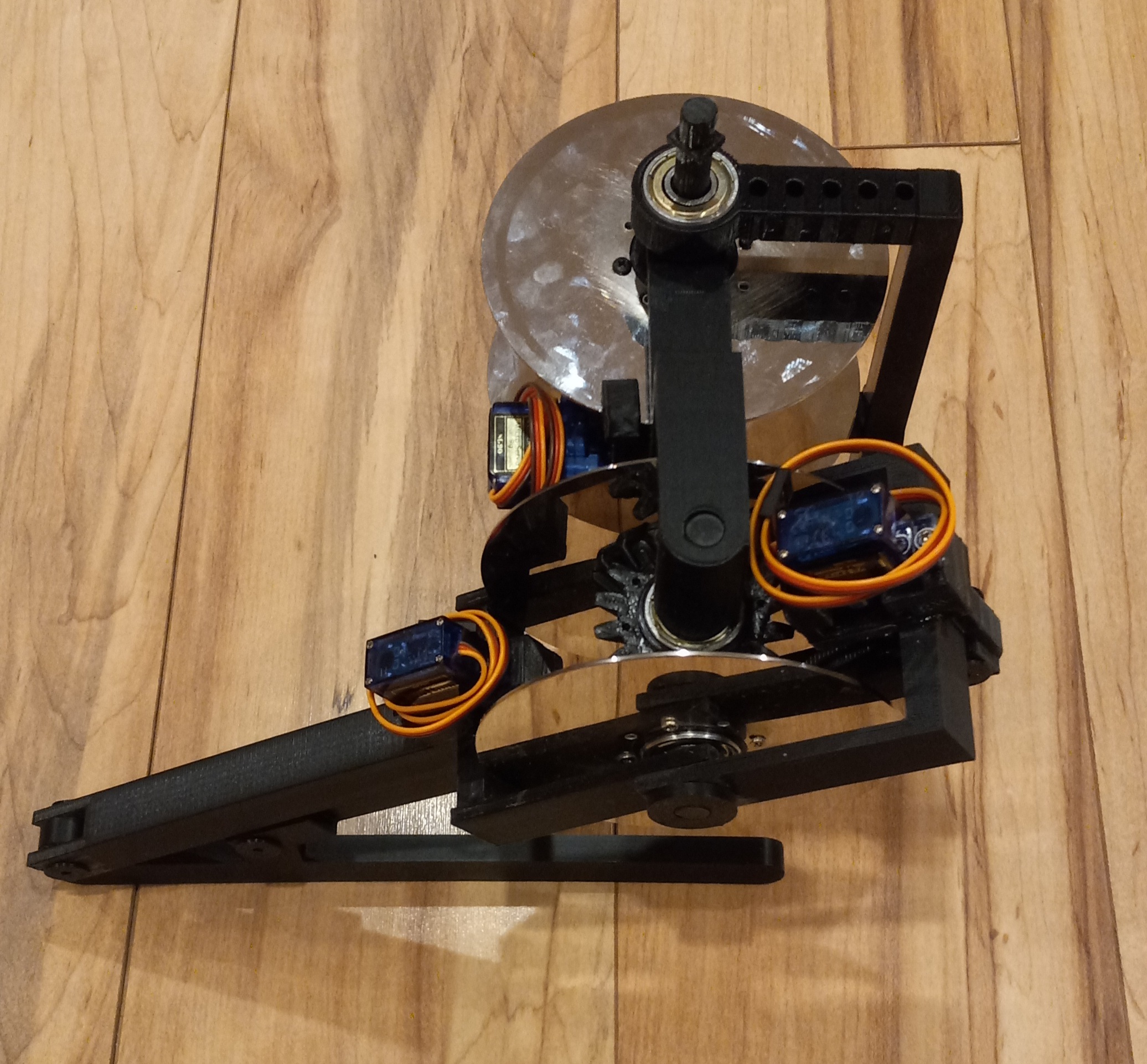
 rand3289
Braker One was born because we need an inexpensive 3D printed backdriveable (compliant) robot ctuator. Here is a video: https://cdn.hackaday.io/files/1719247355596416/BrakerBot_2021-10-10.mp4
This technology can allow construction of biped, quadruped, hex walkers and even rolling robots. It is based on my other project: https://www.thingiverse.com/thing:4327799
There are many approaches to creating robotic actuators. Several of them are available to hobbyists. Servo motors are most common but they are not backdriveable (not compliant). Low gear ratio brushless motor actuators are becoming available but they are expensive and require sophisticated electronics to control them. Distributing power from a single power source through a transmission mechanism such as hydraulics or pneumatics is costly and complicated.
I am going to work on the robot in the following stages.
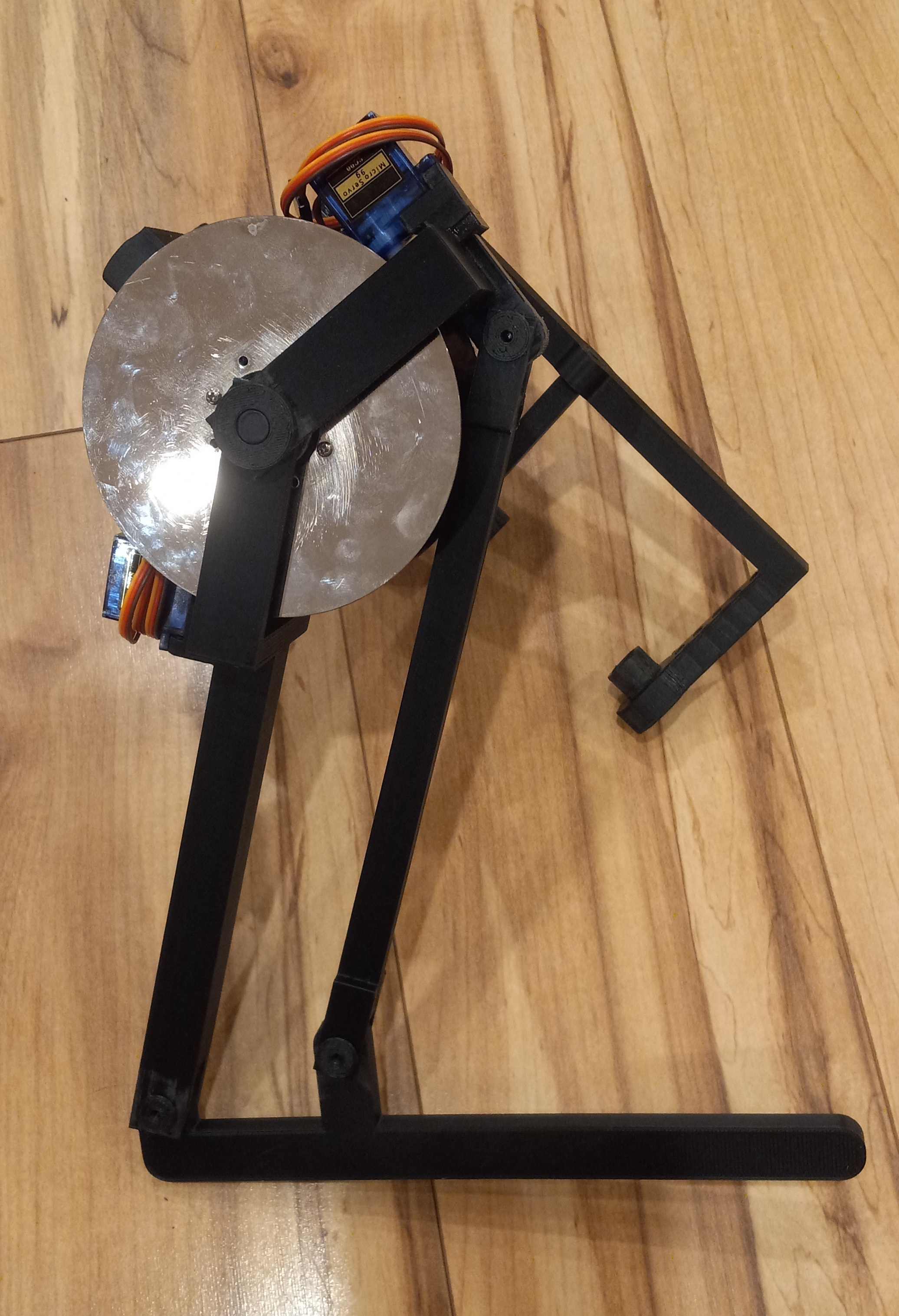
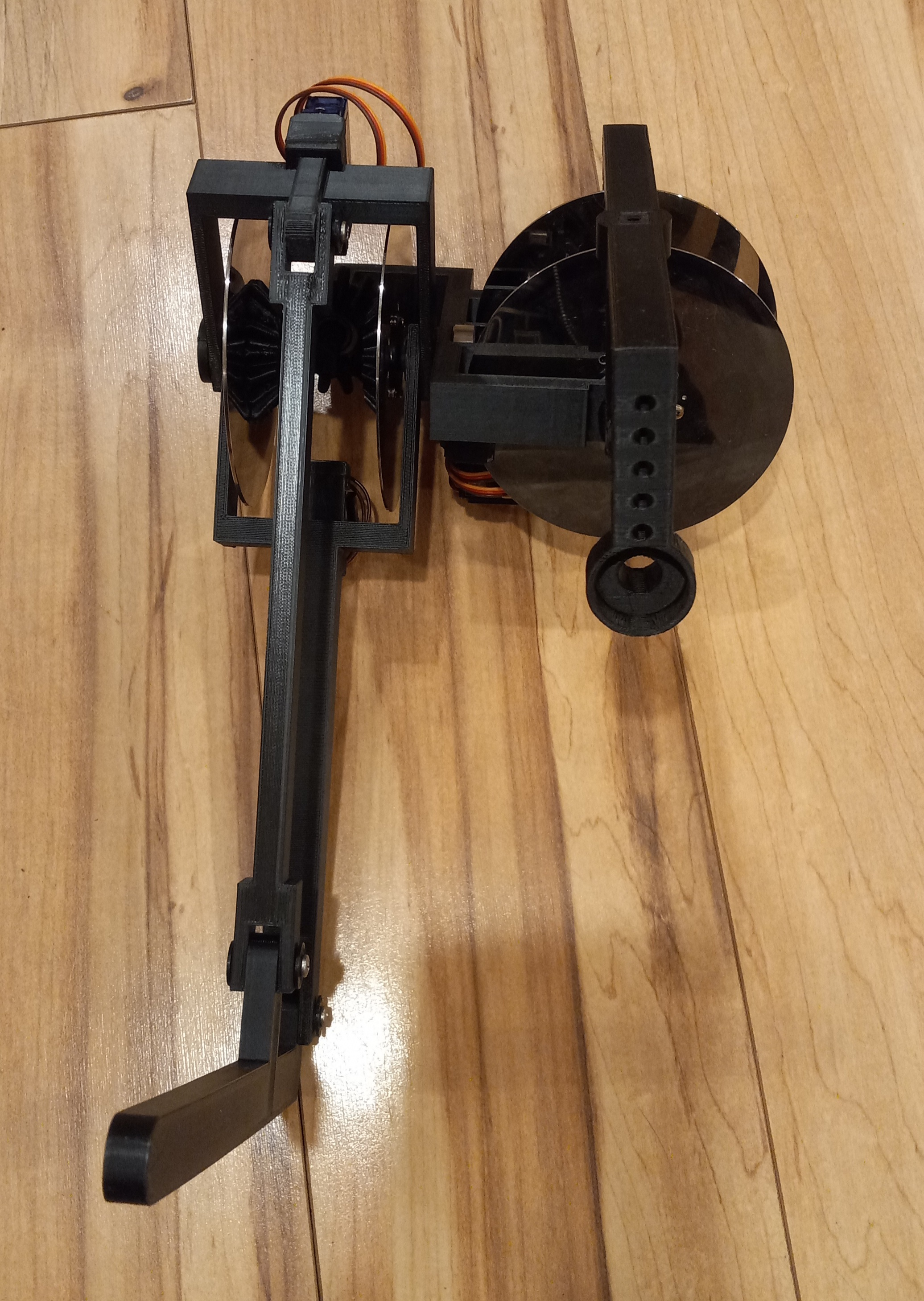
1) Creation of a single leg mounted on a stand with 3 joints and a single geared AC or DC motor without brakes to test the efficiency of the 3D printed mechanism.
2) Creation and testing of Eddy current or electro-mechanical brake/caliper mechanisms.
3) creation of 3D printed joint position, load and other sensors based on FiberGrid technology described here: https://hackaday.io/project/167317-fibergrid
Braking actuator which takes care of the mechanics, is one of many technologies I have been working on for creating affordable robots. Electronics were replaced by my FiberGrid optical sensor framework (https://hackaday.io/project/167317-fibergrid). Control system will be based on my distributed computation framework distributAr (https://hackaday.io/project/167317-fibergrid) simulating an Artificial Spiking Neural Network. The reason I choose a SNN as control architecture is described in my paper "Perception and time in Artificial General Intelligence" (https://github.com/rand3289/PerceptionTime).
All of these ideas are FAR OUT OF THE BOX. I do not expect you to agree with everything I am doing in these projects, but if something clicks, I am looking for constructive feedback or questions. PM me on hackaday or email me toandrey@yahoo.com


 shenzhen
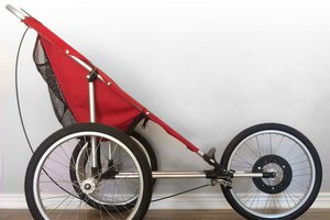
 Scott Swaaley
Interesting.
Can you make one of the actuators stop rigidly in one position while the rest still rotate? I don't mean just not drive that actuator, but make it solidly keep one position?