 Enrico Miglino
Tested and Working
After a number of tests and revisions – involving several software updates – the Raspberry Pi shield to control the on-fly operations (image capture, data processing, data transmission to the ground station) is stable and following the bench tests it works fine.
An important change I have done is the use of the original PiJuice HAT instead of the previously mentions UPS power supply. The reason is the difficult to receive the batteries for the power supply I initially considered to use (I am still waiting for the batteries delivery). Introducing the PiJuice HAT (all the software and hardware documentation can be found on the PiJuice GitHub repository) also got me the possibility to start the drone operations of the flying module easier and automatically.
The Shield Prototype
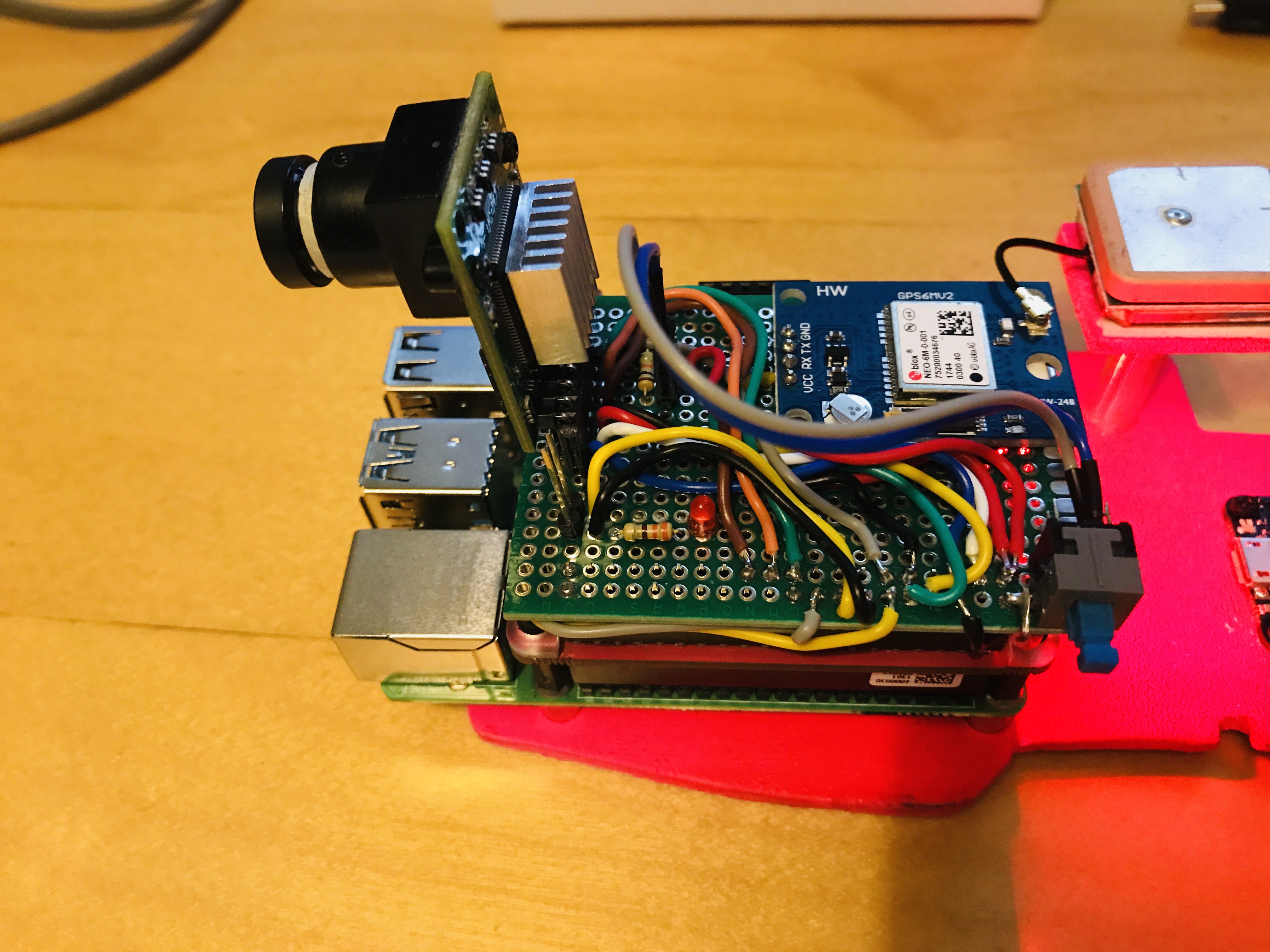
Above: the final version of the Raspberry Pi Nanodrone shield
The small board hosts the camera and the GPS but also includes a LED used to signal with different blinking sequences the current operation and a switch. When the program is running it remains in standby until the switch is not pressed. The application is launched by a bash shell script controlled by one of the two buttons of the PiJuice HAT (the Nanodrone shield is inserted on top).
A Simple PiJuice Configuration
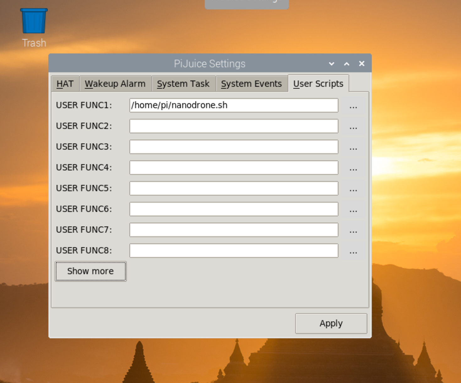 | 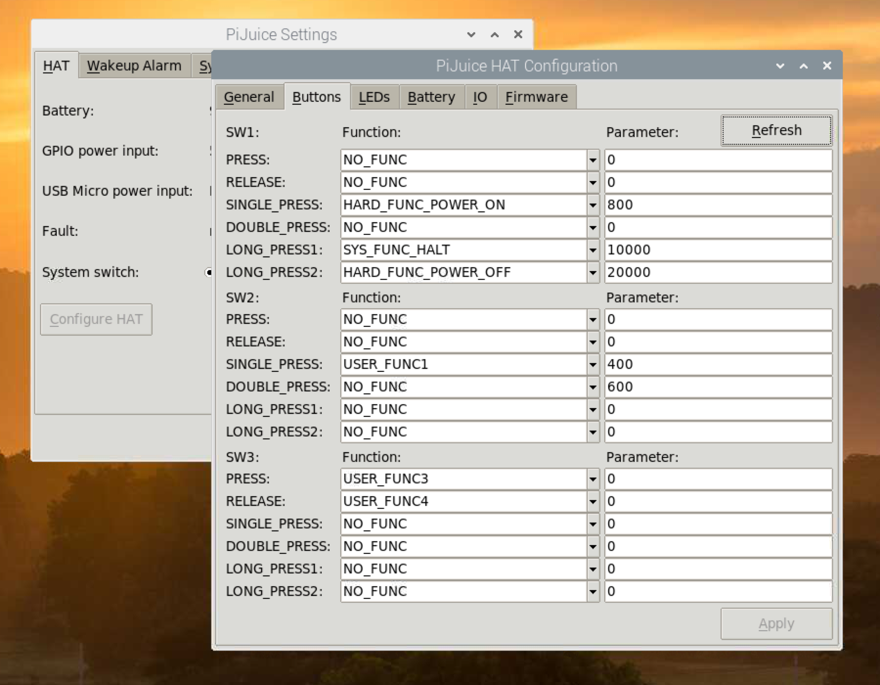 |
The two screenshot above shows the simple configuration of the PiJuice: on the left I defined the bash command to launch the Nanodrone application as User Function 1; on the right the User Function 1 is associated to the switch SW2 of the PiJuice board (the external one).
The Circuit
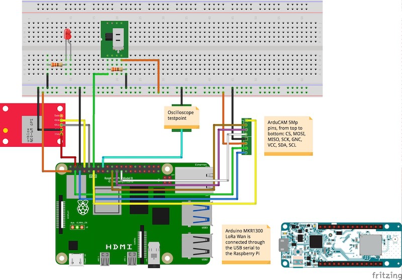
The above image shows the schematic of the circuit. In the definitive design I also kept the two testpoint pins for future performance tests.
The Software Logic
When the PiJuice user button SW2 is pressed the program is started. On startup the signal LED flash once 50ms just to sigal that everything is ok until this point. Then, all the time-consuming operations are executed during the startup phase: hardware checking, GPS initialization, camera initialization and setup (resolution, jpeg mode, etc.)
After the initialization completes, the LED start flashing 50ms every second; it is the signal that the program is running and checking continuously if the switch has been set to on. The system is ready to fly.
When the switch is set to the on position the LED start flashing for 18 second at different frequencies: it is a countdown to give to the user to start the drone and move it in the initial position. When the countdown finishes, it is acquired the first image.
The acquisition process continue until the switch is not set to the off position; it is expected to be done when the drone lands. This logic is implemented in the first program for test fly firstfly available in the GitHun Nanodrone repository.
Discussions
Become a Hackaday.io Member
Create an account to leave a comment. Already have an account? Log In.