 Tim Ryan
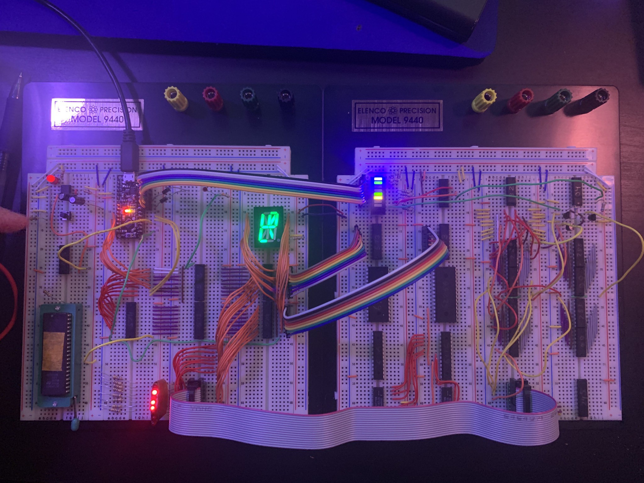
Another in-progress photo. Here you can see a 16-bit value being loaded from “ROM” (which is substituted with an Arduino for now) into the Top-of-Stack (TOS) register. The TOS register is connected to the green 16-segment LED display on this breadboard. There are three reasons for including this display:
The first benefit of this display is that it gives a super easy way of referencing what value the TOS register currently has.
The second benefit is that by loading specific values into TOS, you can make the alphanumeric display show a single character at a time, for example, stepping through the letters “hello world”. Unlike ASCII, where letters are encoded sequentially, the values that correspond to each letter on this 16-segment display depend on how you wire the component. Unlike ASCII, this character encoding is entirely specific to this circuit. Instead I’ve taken to calling this character set it “TOMSCII” in the codebase 😉
The third benefit of this display is that the output pin of this component is essentially a 16-bit OR gate composed of DTL logic (diodes). This allows us to implement a JumpIf0 opcode: if the output of the display is 0V, this means none of the bits in the register are set. By boosting the output voltage we can use this as input to a flip flop that controls whether we jump or advance the program counter each clock cycle.
Discussions
Become a Hackaday.io Member
Create an account to leave a comment. Already have an account? Log In.