 Lightning Phil
Here lies some of the issues I've tripped over:
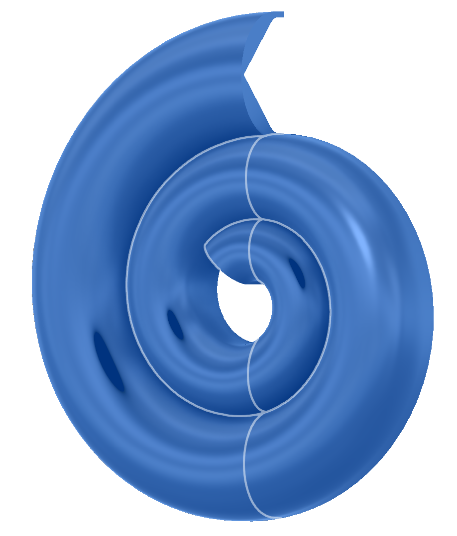
Initial attempts to use an exponential taper for the transmission line meant lofting between 1 surface and another did not come up with equal distances between the sides of the spiral. So work around included making 2 spirals, extruding the shape between them and rounding the edges. This wasn't flexible but did generate the first images and print. Moving to an r squared based spiral allowed for a linear taper between profiles and thus the loft function to work. Figuring that out took many hours as I belligerently wanted an exponential taper. However, by having the width of the inner/terminus smaller in all directions (width and height), than the inlet, a squared relationship can be gained in cross-section area as the line narrows. Looks cool too.
A spiral made of splines has issues at it's ends regarding curvature from Fusion's prospective, for Fusion's own reasons I can't fathom. See below for a curvature analysis of the spline. All's good apart from the centre where it goes wild.
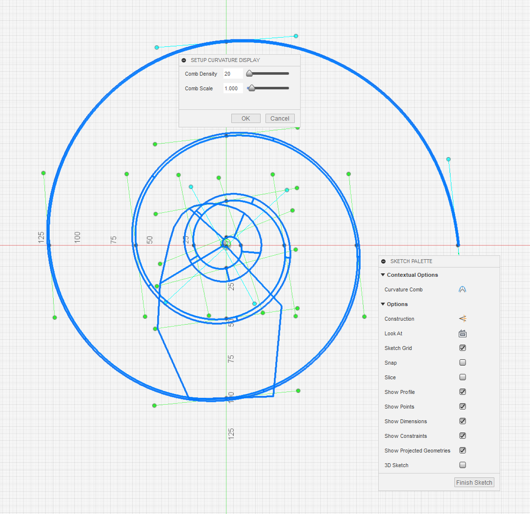
The solution, when wishing to perform a loft from one profile to another is to draw a spline that's longer than needed, then use the create a plane along path tool and not put the planes at the ends - allowing a smooth curve right through the planes of interest.
More faff is caused by Fusion not liking bodies that intersect themselves (which do work sometimes, causing confusion). The solution to that was to use a handy plane (the inlet at the top), to slide the body apart. This is essential as neither simply drawing the objects intersecting themselves or offsetting the outer surface for pleasing overlap were always possible without this.
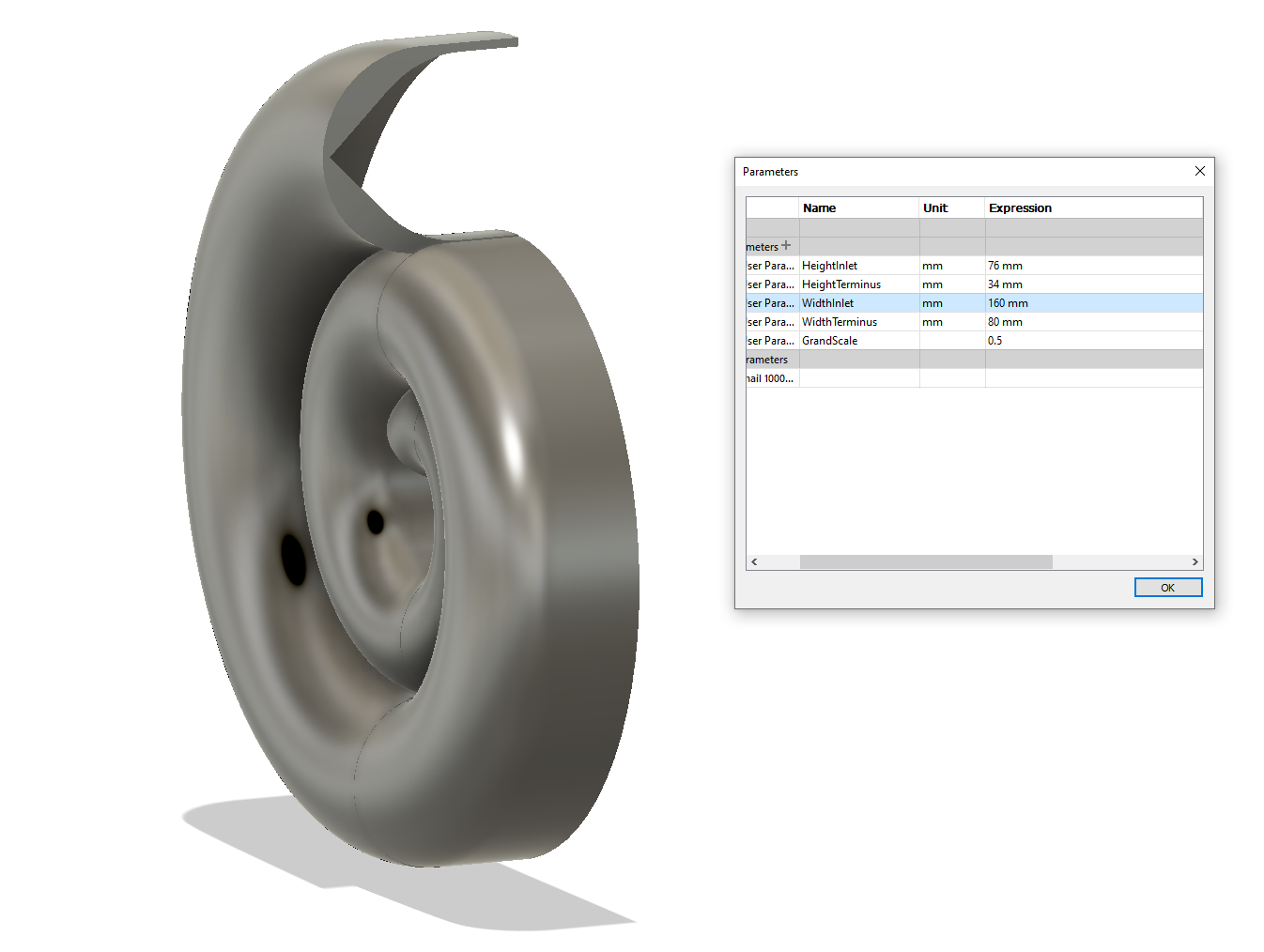
And probably the final part for today is the use of parameters which this project has encouraged. Even though the profile has been split, thickened and scaled, it's still trivial to change the dimensions for a pleasing result - see the difference between the above and below images.
Naturally, I was tempted to call all the dimensions Foo1 to Foo5, but that's because I'm a fool. More sensible names have been chosen, which obviously I'll be glad about if I come back to the project. Width is on the left/right axis. Height for the inlet is up/down, as it is for the terminus when looking it it's profile, even if it is at a bit of an angle now. GrandScale is applied after doing the rest of the drawing to make it small enough to fit onto a printer build platform. From here, I'll juggle the numbers about a bit as the speaker mount is developed.
Here I'll also note the shape of the interior of the profile. It's not rounded, more pent roof. This means no more support. Hurrah!
Randomly - there will be a plinth made to fit with speaker connectors and the crossover within it. A hole shall be drilled in the base and wires poked through for connection. As there will almost certainly be dampening material in it, this may have to be done before assembly.
Discussions
Become a Hackaday.io Member
Create an account to leave a comment. Already have an account? Log In.