Close
0%
0%

SMAFDAPs (Smart Apps For Dumb Alarm Panels)

Use 3 amplified LEDs to sense alarm status LEDs. Send the status to the internet and Smart Apps using Arduino with Wifi shield.

Similar projects worth following
Do you have an alarm system thats not connected to the internet? This project enables access to the status of the alarm via the internet. Check SmartThings app, Alexa, or Google home for the status of your alarm. Or look at the simple web page for status.

The way this is accomplished is using 3 amplified LEDs to sense alarm status LEDs. Send the status to the internet and Smart Apps using Arduino with Wifi shield.

To make it easier to set the thresholds, I'm planning on using 3 Leds to sense, and 3 Leds to show when a potentiometer has been turned enough to enable a transistor for each LED. This way the thresholds can be set without having to change any Arduino code.

Hardware, LED sensor circuit, Version 1

Entunassas Contribution 6 (09 Jun 2020):

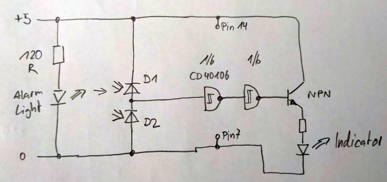
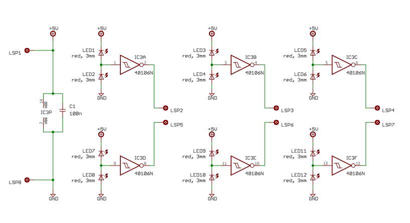
This is Version 1 of the sensor schematic.
"LSP" are connection points to solder a cable to (german expression is Lötstützpunkt, hahaha)
LSP1 = +5V from ARDUINO
LSP2, 3, 4, 5, 6, 7 = Outputs, shall be connected to digital inputs of ARDUINO
LSP 8 = Ground (0V) from Arduino.

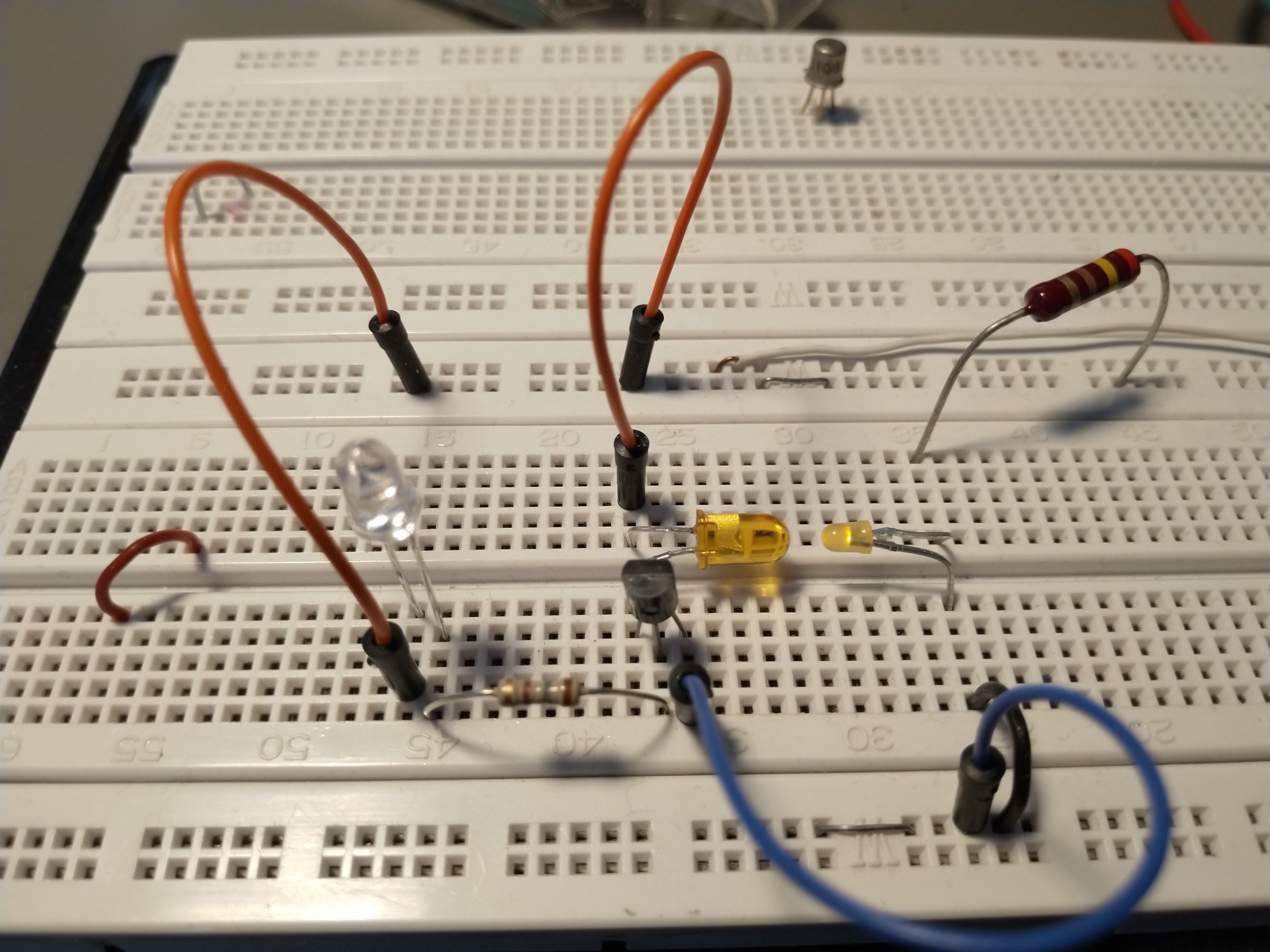
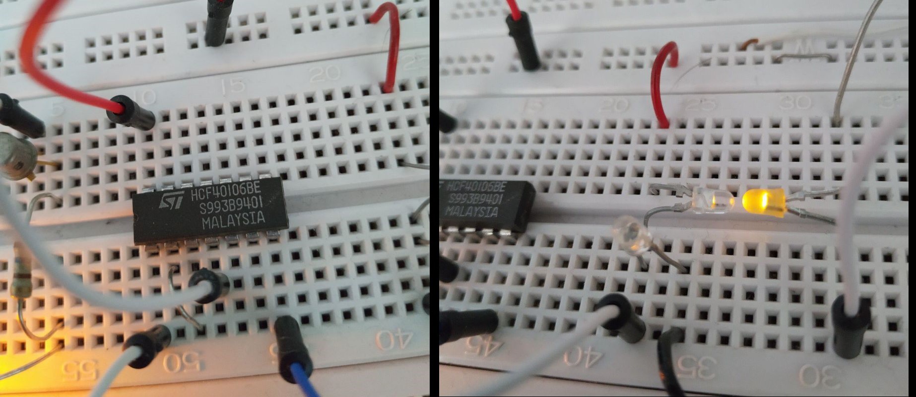
One have to consider the ambient light falling onto the Sensor LEDs should be nearly equal. Also the ambient light shall be low compared to the STATUS LEDs light. Therefore you have to dim the ambient light influence.

A calibration is needed for each sensor. To get familiar with the behaviour of this circuit, do some tests with your individual assembly.

Try influence of

  • ambient light
  • STATUS LED brightness
  • dim/shadow the not used SENSOR LED

(Find the final schematic V1 in section "Files" as PDF also.)

-/-

SMAFDAP_schematic_V1.pdf

(related to contribution 6) Version 1 of the sensor schematic. "LSP" are connection points to solder a cable to. LSP1 = +5V from ARDUINO LSP2, 3, 4, 5, 6, 7 = Outputs, shall be connected to digital inputs of ARDUINO LSP 8 = Ground (0V) from Arduino

Adobe Portable Document Format - 26.96 kB - 06/09/2020 at 20:02

Preview
Download

VID_C5.mp4

Test of Sensor (related to contribution 5).

MPEG-4 Video - 10.70 MB - 06/07/2020 at 08:16

Download

VID_C4.mp4

Test of Sensor (related to contribution 4).

MPEG-4 Video - 8.66 MB - 06/07/2020 at 08:15

Download

IMG_2678.MOV

Basic LED light sensing test

quicktime - 23.10 MB - 05/30/2020 at 06:08

Download

  • 1 × Arduino (could be other micro or en ESP)
  • 12 × LED, clear housing, red light, 3mm You will need 2x LED for each sensor unit (up to 6x2 pcs for the whole thing)!
  • 1 × Wall wart 5 Volts / 5 Watt
  • 1 × CD40106BE Logic IC 6x Schmitt Trigger Inverters (for up to six independent sensor circuits!)
  • 1 × CerCap 100nF / 50V Capacitor for filtering and blocking spikes (soldered next to DIL Socket)

View all 10 components

  • Oath 2.0 example I found

    Eric Livesay06/15/2020 at 04:37 0 comments

    Im waiting on my parts which should arrive this week. In the meantime I found this additional example which might work if We want to make the alarm Status secure: https://github.com/8bitkick/ArduinoGoogleAPI/blob/master/GoogleAPI.ino

  • Found some example wifi shield code

    Eric Livesay06/09/2020 at 03:13 0 comments

    I'm not sure if I mentioned the wifi shield will be needed. I found some great examples of using the wifi shield to communicate with the internet. Here is a page which talks about setting up the wifi code: https://www.arduino.cc/en/Tutorial/WiFiWebClient

    /*
      Web client
    
     This sketch connects to a website (http://www.google.com)
     using a WiFi shield.
    
     This example is written for a network using WPA encryption. For
     WEP or WPA, change the Wifi.begin() call accordingly.
    
     This example is written for a network using WPA encryption. For
     WEP or WPA, change the Wifi.begin() call accordingly.
    
     Circuit:
     * WiFi shield attached
    
     created 13 July 2010
     by dlf (Metodo2 srl)
     modified 31 May 2012
     by Tom Igoe
     */
    
    
    #include <SPI.h>
    #include <WiFi.h>
    
    char ssid[] = "yourNetwork"; //  your network SSID (name)
    char pass[] = "secretPassword";    // your network password (use for WPA, or use as key for WEP)
    int keyIndex = 0;            // your network key Index number (needed only for WEP)
    
    int status = WL_IDLE_STATUS;
    // if you don't want to use DNS (and reduce your sketch size)
    // use the numeric IP instead of the name for the server:
    //IPAddress server(74,125,232,128);  // numeric IP for Google (no DNS)
    char server[] = "www.google.com";    // name address for Google (using DNS)
    
    // Initialize the Ethernet client library
    // with the IP address and port of the server
    // that you want to connect to (port 80 is default for HTTP):
    WiFiClient client;
    
    void setup() {
      //Initialize serial and wait for port to open:
      Serial.begin(9600);
      while (!Serial) {
        ; // wait for serial port to connect. Needed for native USB port only
      }
    
      // check for the presence of the shield:
      if (WiFi.status() == WL_NO_SHIELD) {
        Serial.println("WiFi shield not present");
        // don't continue:
        while (true);
      }
    
      String fv = WiFi.firmwareVersion();
      if (fv != "1.1.0") {
        Serial.println("Please upgrade the firmware");
      }
    
      // attempt to connect to Wifi network:
      while (status != WL_CONNECTED) {
        Serial.print("Attempting to connect to SSID: ");
        Serial.println(ssid);
        // Connect to WPA/WPA2 network. Change this line if using open or WEP network:
        status = WiFi.begin(ssid, pass);
    
        // wait 10 seconds for connection:
        >span class="br0">(10000);
      }
      Serial.println("Connected to wifi");
      printWifiStatus();
    
      Serial.println("\nStarting connection to server...");
      // if you get a connection, report back via serial:
      if (client.connect(server, 80)) {
        Serial.println("connected to server");
        // Make a HTTP request:
        client.println("GET /search?q=arduino HTTP/1.1");
        client.println("Host: www.google.com");
        client.println("Connection: close");
        client.println();
      }
    }
    
    void loop() {
      // if there are incoming bytes available
      // from the server, read them and print them:
      while (client.available()) {
        char c = client.read();
        Serial.write(c);
      }
    
      // if the server's disconnected, stop the client:
      if (!client.connected()) {
        Serial.println();
        Serial.println("disconnecting from server.");
        client.stop();
    
        // do nothing forevermore:
        while (true);
      }
    }
    
    
    void printWifiStatus() {
      // print the SSID of the network you're attached to:
      Serial.print("SSID: ");
      Serial.println(WiFi.SSID());
    
      // print your WiFi shield's IP address:
      IPAddress ip = WiFi.localIP();
      Serial.print("IP Address: ");
      Serial.println(ip);
    
      // print the received signal strength:
      long rssi = WiFi.RSSI();
      Serial.print("signal strength (RSSI):");
      Serial.print(rssi);
      Serial.println(" dBm");
    }

    The next step will be to connect to the google sheet. I plan on using an HTTP Post to post to the Google sheet. Here is some example code for that: (from here: https://www.arduino.cc/en/Tutorial/WiFiWebClientRepeating) - I'm modifying it some as I go on this example: 

    // this method makes a HTTP connection to the server:
    void httpRequest() {
      // close any connection before send a new request.
      // This will free the socket on the WiFi shield
      client.stop();
    // I want to update this to goto a Google Sheet for example like...
    Read more »

  • Excited to have another person helping!

    Eric Livesay06/09/2020 at 02:45 0 comments

    I am excited that another person is contributing. Pretty cool! Thanks for the help!  So I just added a quick high level diagram of the end goal of the project. I will also try to get some code completed (or pseudo code at least) for the Arduino -> Google Sheets part of this. With Entunassa helping with the circuit, I thought I could make some progress on the internet connectivity side of things. I have to order some more parts so while I am waiting on those I will be working mockups/ pseudo code for some of the smart components. 

    The idea is that once the LED circuit is setup and calibrated, the Arduino will sense the status of the LEDs and send that info to a Google Sheet. Why a Google sheet? Its free, and it is on the public internet. This is a way to see the status of the alarm when you are not at home because it is on the public internet. But the Google sheet is just a place to capture the info. To display the status, there are multiple options. You can use a google site (also free) which has some javascript to look at the Google sheet entries and displays the last status at all times on the web site. Or option 2, you can create a Smart App to show the status. I want to try both option 1 and option 2. I have a Samsung SmartThings Hub and i want to create a SmartApp and SmartDevice registered that will show the status of the alarm. Also, I have Alexa so i hope to make an Alexa skill to tell me and show me the status via the Alexa app and Alexa devices (like the Echo, etc.)

  • Testing the sensor circuit

    Entunassa06/05/2020 at 18:05 2 comments

    Entunassas Contribution 1 (02 Jun 2020):

    Hey Eric, thanks for team working here. ☺ Hi, I´ve tested the following:

    Yellow LED at the right may represent the STATUS LED (3mm yellow, matte). In their opposite a yellow LED as a sensor, followed of a small amp. circuit. STATUS LED is driven by 5V over 120R (15...20mA).

    The circuit. I choosed a darlington NPN for amplifying the microamperes from the sensor. First Result: Didn´t work, indicator LED is glowing really poor (it´s current is *way* lower than expected: << 0,1mA), even if i reduce the gap between the LEDs to zero. -/-


    Entunassas Contribution 2 (04 Jun 2020):

    I total the circuit works: If I let glare a bicycle headlight onto the sensor LED, the indicator shows a full light ( = ON). Unfortunately, we have a poor light source to detect. I´ve tried to improve the circuit:

    I have added a second transistor; this assembly acts as a triple-Darlington circuit.

    The current senitivity of it is extremely high, in fact, but the indicator LED even shows a tenuous glow. I predict we´ll run into a problem when using a LED as a sensor. We need more amplifying then a single transistor (and also two in a row) can offer.


    Entunassas Contribution 3 (05 Jun 2020):

    Hmm, neither the DARLINGTON, nor the SZIKLAY circuit will match our needs. You wrote in the discussion: " [...] another transistor in a traditional way (after the amplification) to 'enable' a transistor which would then let the status indicator led light up." This was my idea with the above shown circuitry: Getting the highest possible current amplification from two transistors, which should be >1000 from the left one, multiplied with around 400 from the right one. I can´t believe that there is something wrong - if I touch the Sensor-LEDs legs gently with my finger, that minimal current lasts to light the indicator very well. Maybe the LEDs are scrap. I´ll check other combinations.

    You have mentioned the Texas Instruments "Boomer" LM4675. Its purpose is to drive an 8 Ohms speaker pair. The chip has no extensive current gain but a power stage. I would say it is not suitable for what we want to do.

    I had googeled around and found a circuit using a simple CMOS stage (CD40106 Schmitt Trigger), but I can´t retrieve that page 'cause I forgot to save the link (how silly).
    I have payed attention, however and hope to bring up a test result in my next contribution ☺.

    Entunassas Contribution 4 (07 Jun 2020):

    I´ve tested the circuit from C. 2 with another SENSOR LED. It is working after a fashion, it is neither full ON nor completely OFF. See video footage VID_C4 under "files". Not suitable for you! I would discard that path.
    As mentioned in C. 3, there is a further idea, stolen from another website (:laugh:) ...


    Entunassas Contribution 5 (07 Jun 2020):

    I patched that on my bread board.

    (Readers may ask themselves: Why has Entunassa all these parts at home? Answer: Simply collected from projects over decades).

    OK, does it work? See VID_C5 under "files".

    How does it work? Referring to the IC 40106 datasheet (PDF) we are told it has a FET input, which draws no current from the connected circuit.

    We start wit the SENSOR diode. Power Supply is 5V. There are two identical LEDs in a row, both are drawing a tiny current. The resulting circuit could be depicted by two super-high-ohm resistors in series. This point between D1 and D2 (called INPUT) shows 1/2 of the 5V (regarding Ohm's Law), assumed both LEDs (D1, D2) are illuminated in the same brightness.

    If the SENSOR LED (D1) receives more light, eg. from the DAP (dumb alarm panel), its internal current rises (its imaginary 'resistor' goes down) and the resulting voltage on INPUT rises.

    If ambient light changes, it has alsmost no effect, because both LEDs are affected (no ratio change of their internal 'resistors'). Nevertheless a sharp tuning will be necessary to find the suitable...

    Read more »

View all 4 project logs

Enjoy this project?

Share

Discussions

Michael Taggatz wrote 01/17/2021 at 00:05 point

Hi Eric,

I think it's a great idea. It occurred to me spontaneously that if you wanted to forward an alarm message from more than just one location, you could use a small cheap ESP32 board with an Arduino MQTT client at each location instead of the Arduino with Wifi shield and send the message to a central Raspberry running an MQTT broker. Of course, the Raspberry would also need an MQTT client so that it can evaluate the alarms that arise and forward them as an email or message to a smartphone or PC. The Eclipse Paho MQTT Python client library would be a good choice for the Raspberry, because Python can easily be used to control the processing of the alarms.

Greetings Micha

  Are you sure? yes | no

Eric Livesay wrote 01/17/2021 at 00:24 point

Thank you sir! Thats a good idea :)

  Are you sure? yes | no

Entunassa wrote 06/05/2020 at 17:34 point

Eric, should we open a 'Log' or continue in 'Details' to have the things ongoing (in a chronologic order)? The comments in 'Discussion' are tend to get confusing.

I don´t have any experience how to "develop and describe" here at hackaday. Would you please decide.
For today, I´m continuing in 'Details'.

  Are you sure? yes | no

Eric Livesay wrote 06/05/2020 at 17:51 point

sounds good. I've never collaborated on here before. I will check into it.

  Are you sure? yes | no

Eric Livesay wrote 06/05/2020 at 17:51 point

logs are good for what you are putting in details though

  Are you sure? yes | no

Entunassa wrote 06/05/2020 at 18:09 point

It´s super easy, see the changes :-)

  Are you sure? yes | no

Eric Livesay wrote 06/05/2020 at 02:10 point

@Entunassa thanks for doing all that! What do you think of using a powerful amplifier chip like http://www.ti.com/lit/ds/symlink/lm4675.pdf?HQS=TI-null-null-digikeymode-df-pf-null-wwe&ts=1591322944227

  Are you sure? yes | no

Eric Livesay wrote 06/05/2020 at 02:58 point

also, still checking the circuit you put there. I mean to use another transistor in a traditional way (after the amplification) to 'enable' a transistor which would then let the status indicator led light up.

  Are you sure? yes | no

Eric Livesay wrote 06/05/2020 at 06:11 point

or a more basic op amp might do the trick too?

  Are you sure? yes | no

Entunassa wrote 05/31/2020 at 15:31 point

I made a small LED test setup on a breadboard - the results are poor. Eric, would you let me participate a little, could contribute / share my test results.

  Are you sure? yes | no

Eric Livesay wrote 05/31/2020 at 16:01 point

sure! Can you share your results?

  Are you sure? yes | no

Entunassa wrote 06/01/2020 at 16:32 point

I can´t send schematics or photos. Would be glad if you would invite me to participate.

  Are you sure? yes | no

Entunassa wrote 05/30/2020 at 17:08 point

Ah, OK. I have tested LEDs as a brightness indicator, but not as a sensor to be actuated from another LEDs light. You hope the dyed plastic housing of the LED filters the "wrong" wavelength and helps to identify the correct color... hmm - interesting :-)
I´m afraid it may not work... the light intensity of status LEDs is often poor and not comparable to "torch-like" 5mm-LEDs.
I will check that here, it´s fascinating.
Also important might be a schmitt-trigger input for the detectors, to eliminate flickering. Do you have a stabilized supply for the detectors also?

  Are you sure? yes | no

Eric Livesay wrote 05/30/2020 at 17:34 point

re schmitt trigger and stabilized supply, im still an electronics newbie. I will look them up thanks for the idea!

  Are you sure? yes | no

Eric Livesay wrote 05/30/2020 at 14:49 point

also regarding LDR, I wanted to avoid adding more things to filter for the different wavelengths. Using the LEDs makes it simpler to respond to the colors I want.

  Are you sure? yes | no

Eric Livesay wrote 05/30/2020 at 14:45 point

Hi, great questions! I was thinking of starting with the leds together at the end of wires just taped at the edge of the panel near the status indicators. Final method may involve velcro adhesive pads. The status LEDS I planned to have on my little board that has the transistors and potentiometers for amplifying the sensed light. This will go on top of the Arduino and wifi shield. The status LEDs are meant only for configuring the thresholds of the sensor Leds. I might put a separate LED indicating the sense circuit is working, I will consider it. Regarding using a phototransistor, if I cant get the the thresholding to work with the leds just using the Transistors and pots, then I will consider that, thanks for the idea! Regarding ambient light, my initial test with a red led seemed to indicate that it wasn't a big issue as it was only responding to another red led. Will have to see as I need to do more testing.

  Are you sure? yes | no

Entunassa wrote 05/30/2020 at 09:24 point

Hi Eric,
I hope I understand it correct: You´ll try to sense the Status LEDs of the alarm base and transmit this information?
Some questions:
Will you glue the sensors onto the case? Or placing a small housing over the Status LEDs (duct taping..?) How to see the Status LEDs at a glance, then?
How do you think to eliminate ambient light influence to the sensors?
Why not trying LDR or phototransistors (more sensitive)?

Looking forward to an interesting discussion.


  Are you sure? yes | no

Similar Projects

Does this project spark your interest?

Become a member to follow this project and never miss any updates