Close
0%
0%

VUHF Radio

A dual band VHF/UHF module based around two AX5043 radios. Built to work with HAM Radio communications using AFSK and G3RUH modulations.

Similar projects worth following
A plug-and-play radio module that I developed to communicate with my University CubeSat that is scheduled to launch next year. The module uses two AX5043 transceiver for dual band, VHF and UHF, communication using AFSK-1200 and FSK-9600 (G3RUH) modulations and AX.25 framing. It is also capable of receiving the Morse Beacon of the CubeSat in VHF.

For now, using the current hardware and software, the module can:
- Receive and transmit AFSK-1200 using AX.25 in both UHF and VHF
- Receive and transmit MSK/G3RUH-9600 using AX.25 in both UHF and VHF
- Receive and decode Morse in VHF
- Output receiving signal tracking info, like RSSI and Frequency Offset
- Basic configuration changes over an CAT-like interface and packets over KISS.
- BPSK-9600 support
- AM and FM demodulation as well as FM modulation (Yes you can listen to FM Radio!)

Background

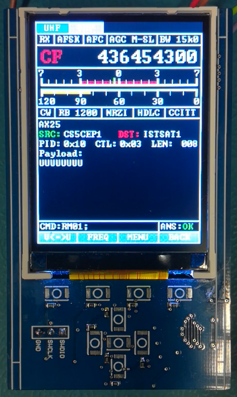
During the development of the TT&C for my University CubeSat I started to think about an easy and cheap way to receive communications from the CubeSat once it is in orbit, projected to be next year in 2021. The CubeSats TT&C transmits in VHF, and receives in UHF, using AFSK-1200 with AX.25 as the basic communication modulation. It also has a Morse beacon in the same frequency band. The idea of the developed module is a plug-and-play receiver that anyone can use to receive the satellites communication without needing any additional hardware or software, besides an antenna.

The module is based around the AX5043 Sub-GHz transceiver, it is as far as I can tell the only transceiver of its kind that supports FM-AFSK. It is an amazing little transceiver, full of functionalities and highly configurable. It even supports analog interfaces (1 DAC and 1 ADC channel) and a raw bit interface (DATA & DCLK)! The module uses two of these transceivers so that it can both receive communications from the CubeSat in VHF and transmit to it in UHF, useful for me during development and testing of the CubSats TT&C. The control and data transfer of the transceiver to/from the PC is done over USB using the Virtual COM Port library of the STM32F103C8 MCU. The module also features current consumption monitoring capability of the module and each transceiver. It also has analog signal conditioning to use the ADC and DAC of the AX5043 for the possible "analog" FM and other analog outputs like RSSI. The module was designed to fit inside a cheap aluminium enclosure (80x50x20mm in size) available on eBay.

Hardware

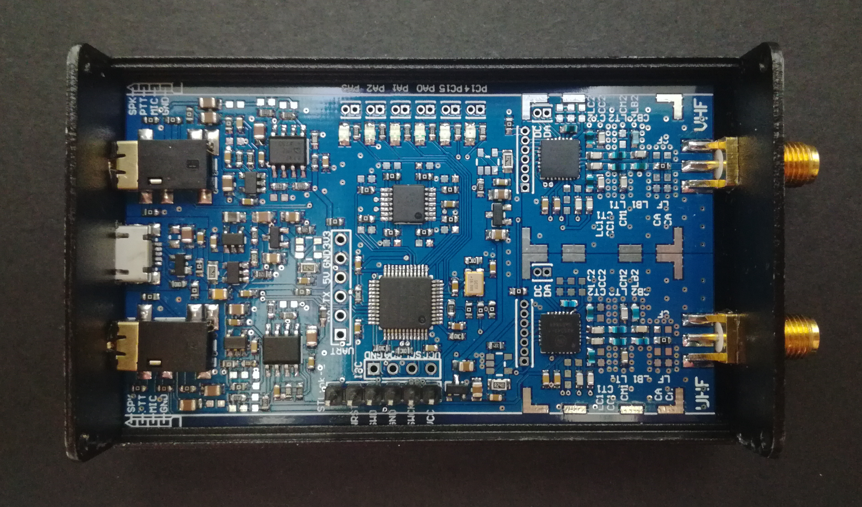
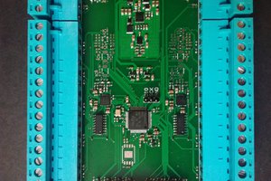
The localization/layout of the different modules can be seen in the image below, each LDO has output current monitoring using a INA138. The analog input/output for each transceiver is done through a 4-pole 3.5mm audio connector. A few "mandatory" LEDs for status indication are also present.

There are some mistakes in the hardware design, visible as wire bodges, diagonal components and bypass/shunt resistors. I'm working on a revised hardware design (Version 3) to fix those and also exchange the XO for a TCXO for much better frequency accuracy and stability.

Results

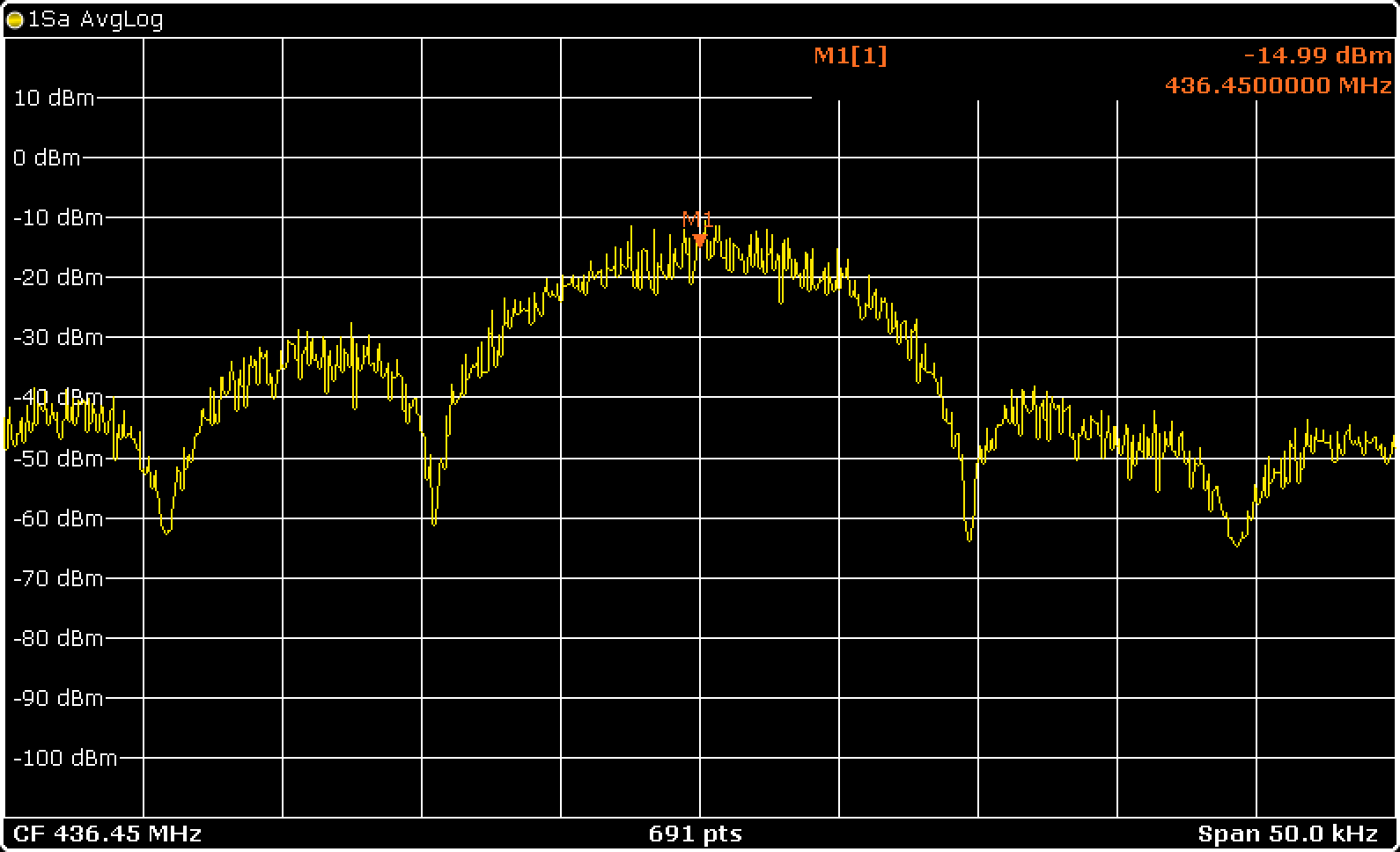
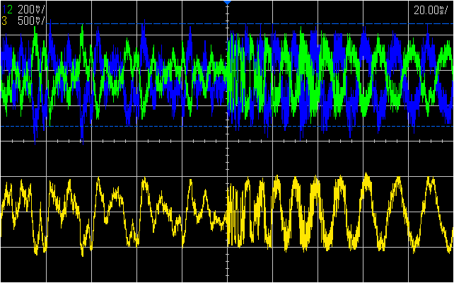
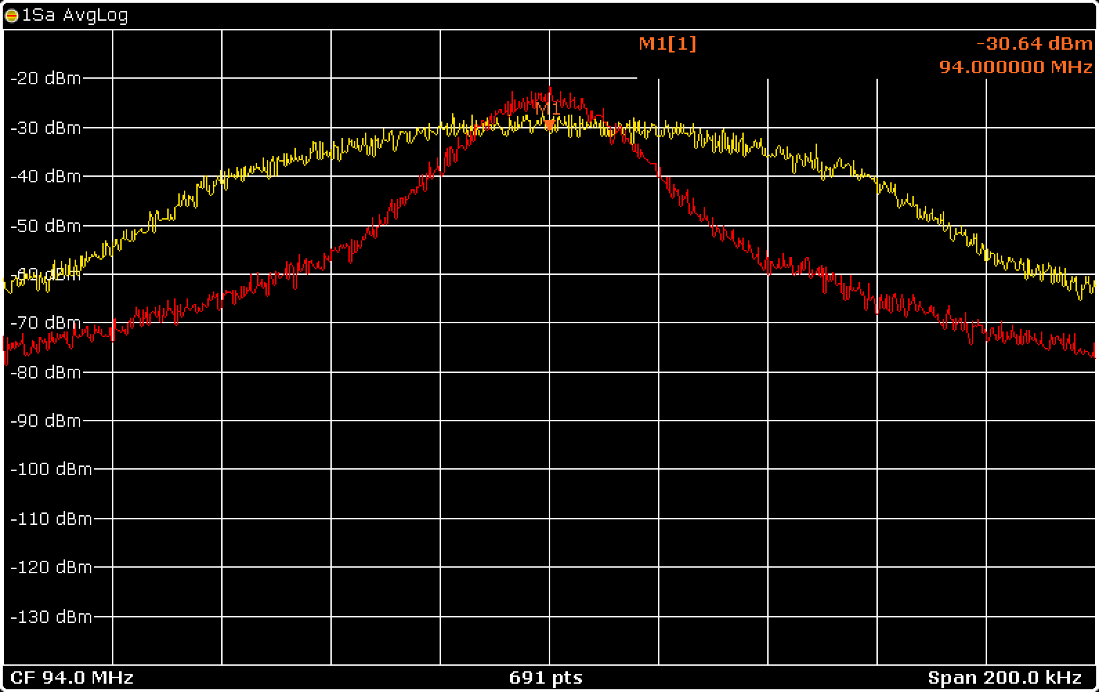
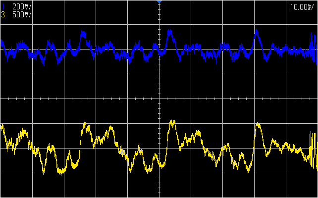
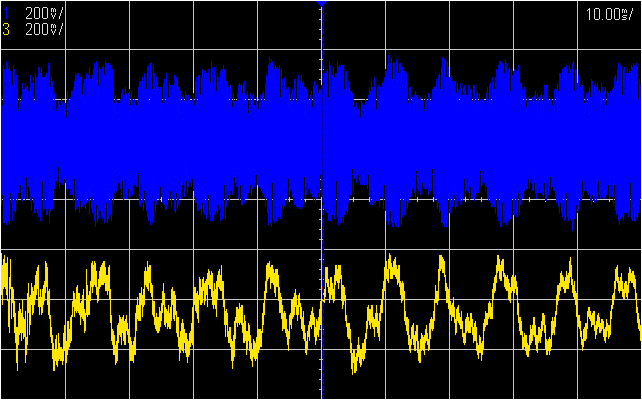
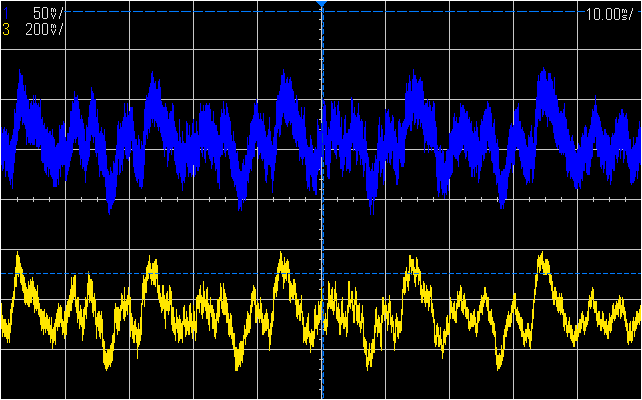
So far I have successfully tested AFSK-1200 reception and transmission as well as FSK-9600 (G3RUH). The transmission spectrum for those modulations can be seen below. The emitted power is around 15 dBm just as expected from the datasheet.

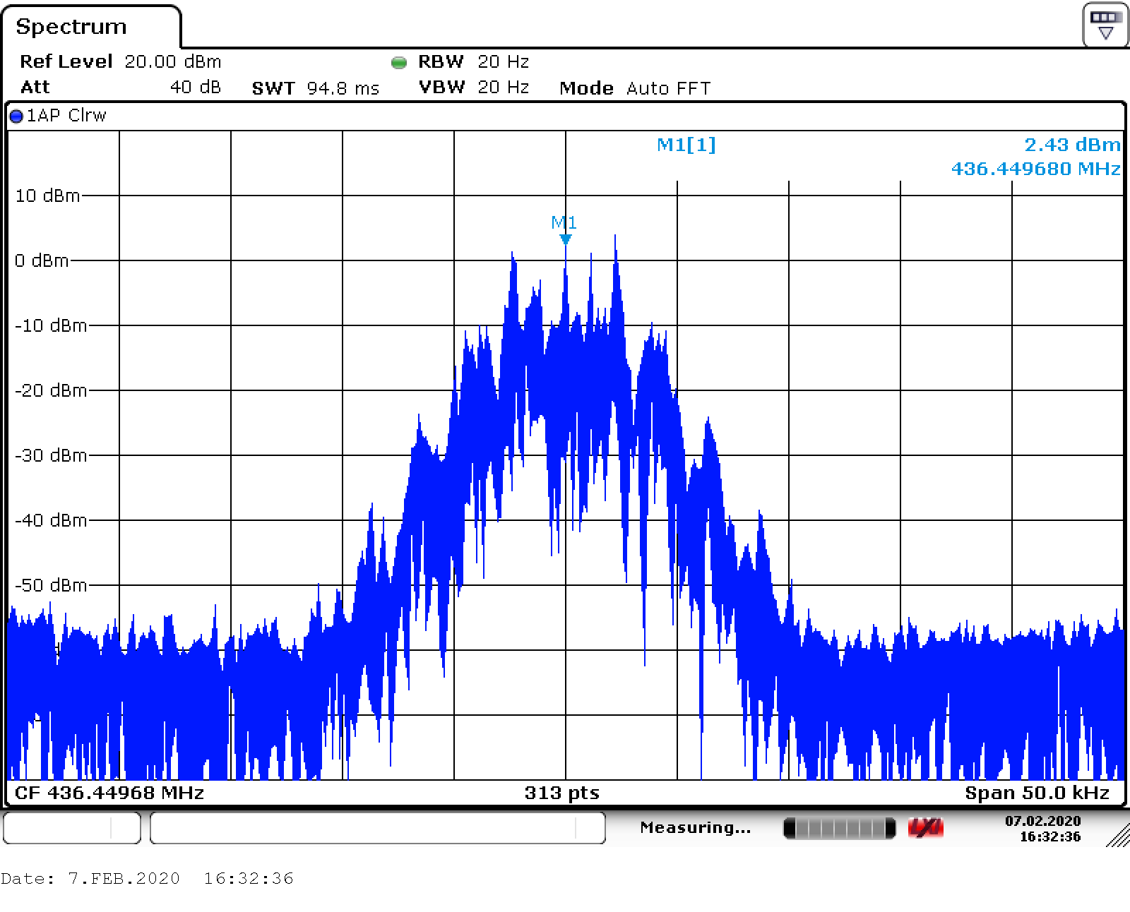
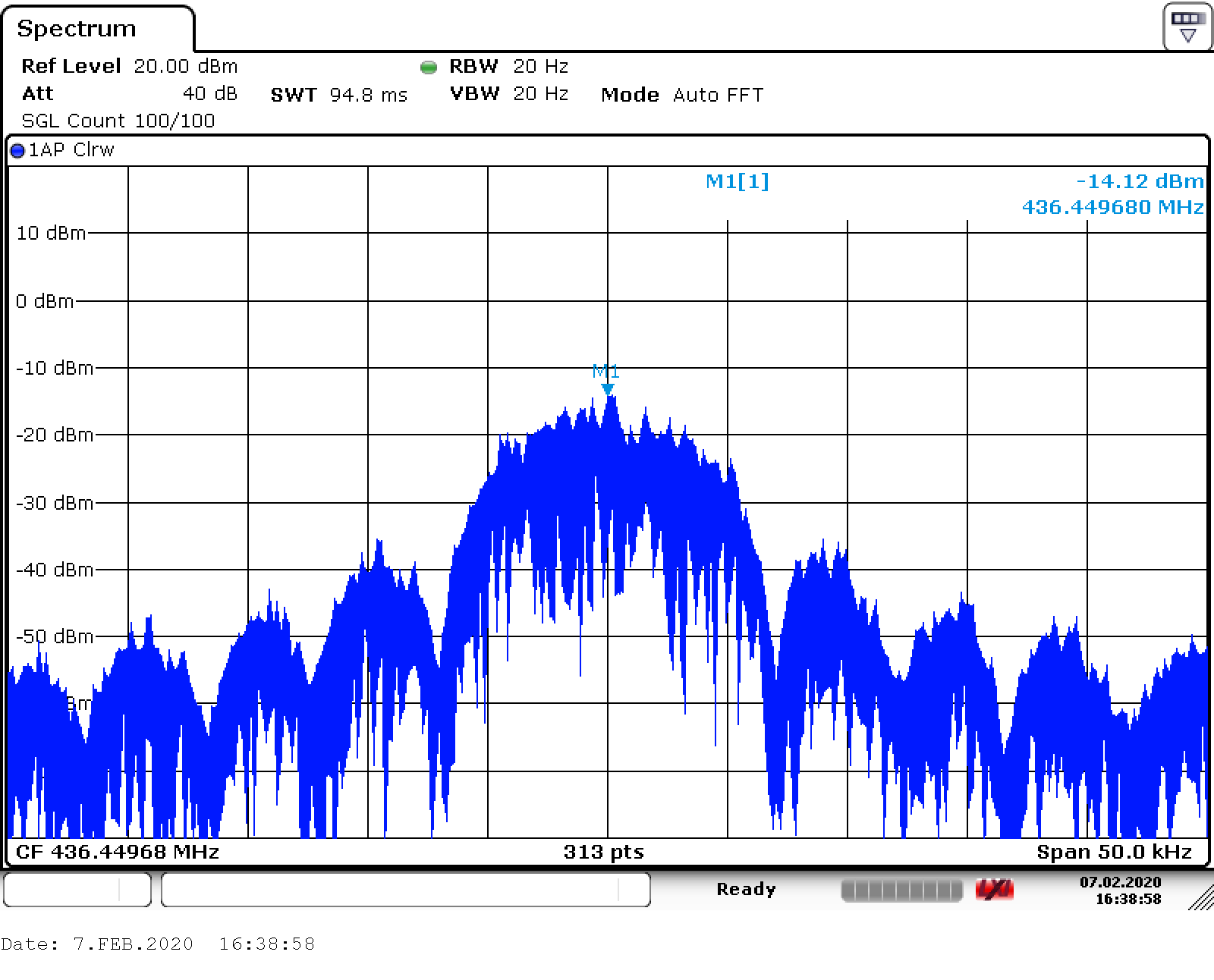
The power consumption during transmission is around 140mW for the transceiver alone which gives a efficiency of about 20%.

Characterization of the reception is still ongoing, so far only AFSK-1200 in UHF is characterized with a BER of >10-5 for input powers over -105 dBm and 10-4 at -110 dBm with similar resutls for GMSK-9600 in UHF. The VHF receiver has significantly worse performance with a BER of >10-5 only at input powers over -95dBm. This requeires further testing.

The current hardware schematic and Gerber files can be downloaded and the current firmware is available on my GitHub page. Fill free to use them however you want. Also more in-depth performance analysis are available on my webpage as well as an explanation on how to set up the AX5043 transceiver which is a bit complex with all the possible configurations.

Adobe Portable Document Format - 1.49 MB - 07/15/2020 at 19:32

Preview
Download

x-zip-compressed - 81.86 kB - 07/15/2020 at 19:32

Download

Adobe Portable Document Format - 1.41 MB - 07/15/2020 at 19:32

Preview
Download

x-zip-compressed - 75.65 kB - 07/15/2020 at 19:32

Download

  • 2 × AX5043 Ultra-Low Power Narrow-Band Sub GHz (27 - 1050 MHz) RF Transceiver
  • 1 × STM32F103C8 Microprocessors, Microcontrollers, DSPs / ARM, RISC-Based Microcontrollers

  • FM Demodulation Revisit

    NotBlackMagic02/07/2022 at 20:14 0 comments

    Finally came back around to revisit the FM demodulation mode of the AX5043, it has been 2 years since the first tests! One of the motivation factors is to get the VUHFRadio module to receive and demodulate NBFM besides the already working WBFM, and also to help the testing/investigate of using the AX5043 for the M17 project.

    The first discovery in this revisit is how the FM sensitivity in receiving mode is set/defined. It turns out it is depended on the set RX BITRATE, which in FM mode is the sampling rate of the demodulated FM signal. The sensitivity is given by the equation bellow (taken from the programing manual as the meaning of the TRKFREQUENCY register) and taking into account that the DAC maximum output range is 1.65V:

    This shows a problem, with low sensitivity the AX5043 will also have low bitrates, which is a problem in NBFM... This problem is well visible in the figure bellow, where all settings are kept the same except for the BITRATE, settings are for NBFM and are the same as for WBFM except with a DECIMATION value of 16.

    This problem can somewhat be mitigated by decreasing the DACSHIFT register value, effectively adding a gain of 2, or more, to the DAC output, but this comes with increased noise at the output.

    The other test that was performed was to see the effect of changing FREQGAINB0 (0x128) which, according to the programming manual, sets the FM Demodulation bandwidth but it does not say in what way. The tests performed show that it more or less follows the following equation:

    An example of the effect of changing FREQGAINB0 (GB0) register is shown in the figure bellow. The settings used are the same as in the previous experiment, the NBFM settings, with the highest used sampling rate of 31.25 ksps, RX BITRATE set to 4096.

    Resumed, it is possible to use the AX5043 for NBFM but with worse performance then with WBFM. Some additional test are planned, with filtering the output signal and with NBFM transmission. Also, the push-to-talk feature that was planned for the VUHFRadio module will be implemented and tested!

    On the website there are some additional results for the above tests, for WBFM, and some additional info. The code with the register settings used for NBFM are not yet added to the code in GitHub but it will follow soon!

  • RadioInterface Update

    NotBlackMagic07/18/2021 at 19:29 1 comment

    The RadioInterface Module software has been updated to now be able to switch between both the two VUHFRadio channels, VHF and UHF, seamlessly. Also, some performance tweaks were done to the SPI driver that communicates with the LCD (ILI9341): removing the CS toggle for every byte transfer and keeping it LOW all the time, the transfer speed was more then doubled.

    Also, a new special feature was added, a Waterfall window. It takes the RSSI and RF tracking variables and creates a Waterfall of it, with a "traditional' color gradient and vertical scrolling! The refresh rate is currently limited to 5Hz as it takes around 150ms to refresh the Waterfall window. The vertical scrolling consumes around 99% of this time as every line has to be read from the LCDs GRAM and written back one line/row further down. The hardware accelerated scrolling included in the ILI9341 LCD driver can't be used as it does not modify the GRAM content and therefore when the vertical scrolling mode is exited, to draw on other parts of the screen, the scrolling is lost.

    There is still has some margin for improvements, specially in the refresh speed, but it is working pretty well and is very useful already. Bellow is a short clip showing the Waterfall Window working, with a frequency sweep at the VUHFRadio module input:

    The updated code of the RadioInterface module is published on GitHub and a new section has been added to the website with some more information.

  • Digital Modulation and AX.25

    NotBlackMagic02/03/2021 at 10:20 0 comments

    With the new RadioInterface add-on board working it was time to revisit the digital modulation/demodulation to tune and integrate them with it. Both AFSK-1200 and FSK-9600 (G3RUH) have been tested again but this time the modulation, TX, was tested using the RTL.SDR + SDR# + SoundModem combo to test that it works with HAM Radios.

    This test can be seen in the short screen recording bellow, for AFSK-1200:

    On the receiving side, the received packets are transmitted over USB and UART using the KISS protocol. The software of the RadioInterface has received an update so that it can receive and decode these packets and display their content on the screens GUI, as can be seen in the Figure bellow:

    I also got back to make BPSK work and finally figured out the problem: There is a dedicated register, MODCFGP (0xF5F), for PSK modulation settings that is not mentioned anywhere in the documentation. I only found out about it in a recent blog post from OnSemi... (AX-RadioLAB configures that register appropriately).

    With this, BPSK-9600 modulation is now also working and the emitted spectrum can be seen in the Figure bellow. The reception side on the VUHFRadio is not as good and need further testing and tuning.

    As always, the software can be found on GitHub and more in-depth information on the website.

  • The First Add-On Board

    NotBlackMagic01/05/2021 at 11:28 0 comments

    Over the last few months I started to develop the first add-on/expansion board for the VUHFRadio Module. This add-on board adds a TFT Screen, buttons and a battery manager IC/circuit so that the VUHFRadio Module can be used portable without a PC. This add-on board was planned since the begging of the VUHFRadio Project and is now finally starting to become reality.

    The add-on module fits on top of the VUHFRadio inside the same enclosure and is connected with two cables, one for the communication over a UART interface and one for power. Bellow is a figure showing this new add-on board with the current GUI (not all that is shown is functional yet):


    As can be seen in the picture, some components have not yet arrived, under them the buttons... The figure also shows the current GUI look. Some functionalities are already implemented and tested, under them showing the current RSSI value, the updating the RSSI bar, displaying the RF Frequency offset, as the green bar, and changing some of the settings like the RX Bandwidth and AGC speed.

    The Module communicates over a UART interface with the VUHFRadio Module and uses the same CAT commands as the Module uses to communicate over USB. I'm working on expanding the CAT commands as needed to get as much of the configurations and settings of the transceivers available over the interfaces. The current CAT command list can be downloaded as pdf from the website.

    The battery managing circuit has not yet been tested, not all needed components have arrived. As soon as I get them I'll post an update.

    A new page was also added for this add-on board with all the design files and a interactive GUI to show better how it looks IRL: Radio Interface and the software is available on GitHub.

    I sometimes post about progress of the GUI development, and other new projects on both twitter and Instagram.

  • FM Audio Modulation

    NotBlackMagic11/12/2020 at 10:18 0 comments

    After getting the Wideband FM Demodulation to work and achieving much better results then expected, it was time to test the FM Modulation mode. The base configuration is the same as used for FM Demodulation.

    In FM Modulation, the internal ADC is used to control the FM deviation/shift. For this the ADC was set-up to use the differential inputs, GPADC13. The Analog Input circuit transforms the single ended AC coupled input into a differential signal in the ADC input range of +/- 500 mV around a VCOM of 800mV.

    Bellow is a figure of this signal conditioning, in yellow is the Analog Input signal, the audio signal injected into the module, and in green and blue the differential ADC inputs.

    This figure also shows a problem with the differential amplifier in use, with the current circuit the amplifier is not very stable and introduces an oscillation on top of the differential output signal. In the future a different amplifier will be used and tested but for now, even with this oscillation, the results are good.

    The sampled signal by the ADC is then used to control the FM deviation. The conversion gain from ADC count to frequency deviation is controlled by the FSKDEV register and here it is set to use the maximum frequency deviation possible, +/- 62.5kHz, which gives the desired Wideband FM Modulation.

    Bellow is a figure showing the RF output spectrum of the Module. The spectrum of the FM Modulation with a full range audio signal as the input, 100% volume from my laptop, is shown in yellow and with a half range signal, 50% volume, in red.

    To listen to the FM Modulation any conventional FM receiver can be used, I used the FM receiver of my smartphone and it worked great! More information on the set up used to achieved this as well as an audio sample file output by my smartphone FM receiver are available on the website.

    With this, the Module can now both modulate and demodulate FM signals. The next step is to test Narrowband operation, using a microphone as the Audio Input signal and implementing push-to-talk functionality.

  • Audio Filter Improvements

    NotBlackMagic10/06/2020 at 11:57 0 comments

    As seen in the last project logs/updates, the module is capable of demodulating and outputting audio FM and AM signals. The audio quality is OK, not very good due to the way the DAC works and the not very good filtering of it. Over the last few days I researched different filter typologies to improve the audio quality and I tested a new one that uses the same circuitry as the previous filter, that is already present in the Module.

    The previous filter used was a double RC Low Pass Filter, as can be seen in the figure bellow on the left. The new one tested is a double LC Low Pass Filter where the resistors of the RC filters are exchanged with inductors, as can be seen in the figure bellow on the right.

    The double RC filter is a second order low pass and the new tested LC filter is a fourth order low pass, increasing the DAC filtering substantially. Bellow is a figure comparing the frequency response of both filters with ruffly the same cut-off frequencies:

    Tests showed that the new LC filter improved the Audio quality as can be seen on the figure bellow where the Audio Output of the Module is shown, when in FM Demodulation mode. This can be compared with the previous project log, "FM Audio Demodulation", figure. The test conditions were the same.

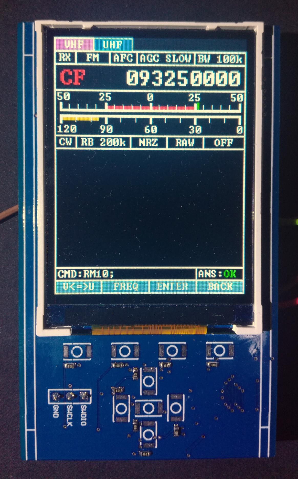
    The improved Audio quality is also audible, a sample is available on the
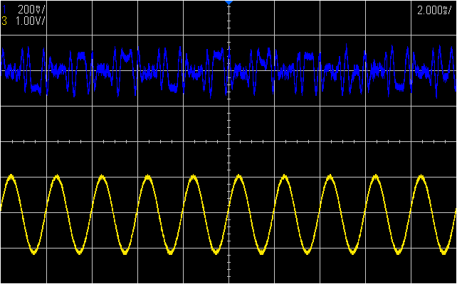
 website, but it has now a lower pitch/tone.

    On the website a more in-depth comparison between the filters used, and two others tested before, was also added.

    Besides this I'm working on a better command interface for the Module, inspired by the CAT command interface used by some HAM Radios like the ones from YAESU and Kenwood. It will not be compatible as it is a very different kind of device but the syntax is the same, eg. Setting the VUHF Radio Frequency command is: "FA145895000;"

  • FM Audio Demodulation

    NotBlackMagic09/02/2020 at 20:04 1 comment

    Analog FM demodulation, and modulation, is a unique and officially supported special feature of this transceiver. ON Semiconductor even provides an application note on how to set up and use the transceiver as an analog FM transceiver, "AX5043 Use as Analog FM Transceiver". Both the application note and the configuration used are for Wideband FM signals, the type used in FM Radio Broadcast. FM Radio Broadcasts were actually used to test the FM demodulation with good success!

    As with the AM Demodulation, the basis of the FM Demodulation is the internal DAC. For FM Demodulation the DAC is setup to output the Frequency Tracking value. With the transceiver setup properly, the FM signal is first down-converted into the IF stage where the frequency change over time is tracked and output by the DAC. This tracking information is also accessible over the SPI interface of the transceiver.

    To show the FM modulation in the IF stage, the DAC was configured to output the SAMPLE_ROT_I (or SAMPLE_ROT_Q) and a RF signal generator connected to the module is used to generate the FM signal, using as the modulating source a pure 500 Hz tone. In the figure bellow the FM signal in the IF stage is shown in blue and the pure 500 Hz tone is shown in yellow.

    With the DAC setup to output the frequency tracking value, the FM demodulation, the signal observed is shown in the figure bellow. In blue is the FM demodulated signal and in yellow the original audio signal used as the modulation source.

    As with the AM demodulation, a lot of noise is visible on the demodulated signal. This noise is also very clearly audible in the audio output of the module, through the audio jack. The main source of this noise is from the not well filtered DAC output.

    Samples of the output audio can be listened to on my website, as well as all the configurations used to achieve the FM demodulation.

    A little teaser on what I'm testing and working on for this project can be seen on my twitter, very early stages still.

  • Audio AM Demodulation

    NotBlackMagic07/26/2020 at 20:15 0 comments

    This very unconventional use of the AX5043 transceiver was triggered by a question posed to me by a fellow Hackaday member, if the transceiver could be, somehow, used as an Audio AM receiver. Over the past week I explored this idea and it turns out that it actually can!

    The basis for this is the very versatile DAC output of the transceiver which, among others, can output the amplitude tracking information of the signal at the entrance of the demodulator block. With the DAC set up to do this, the transceiver has to be "tricked"/setup to keeping the amplitude modulated signal at the IF stage, where this tracking information is calculated. The signal at the IF stage is visible in the figure bellow in blue (DAC set to output either SAMPLE_ROT_I or SAMPLE_ROT_Q), in yellow is the original audio wave:

    With all properly setup, the DAC outputs the demodulated AM signal, the desired Audio signal, as can be seen in the figure bellow. In blue is the demodulated AM signal as output by the DAC and in yellow the original audio wave:

    It can be seen that the demodulated signal is very noise. The main source of this noise is the not well filtered DAC output, even after a second order low pass filter. The transceiver uses a Sigma-Delta DAC. Even with this noise the performance is much better then expected, and by plugging in a headphone to the audio jack of the Module one can listen to AM audio transmissions!

    More information on the set up used to achieved this as well as an audio sample file output by the Module are available on my website.

  • Hardware Revison 3

    NotBlackMagic07/15/2020 at 19:31 0 comments

    The newest hardware revision, revision 3, arrived and I assembled and tested it over the last weeks. This revision fixes all the hardware errors and problems discovered with the revision 2 like the AX5043 Oscillator Input, analog output amplifier/filtering and in the power supply/distribution circuits.

    The RF circuit, matching networks, were kept the same and this is reflected by the RF performance and input matching (S11) which are the same as with revision 2.

    Besides that, the PCB color was changed to blue which in combination with no bodges looks much better and clean then the previous revision:

    With this, I now have two assembled and working modules. This, with the antennas that arrived and where tested a few weeks ago, enables now communication testing between modules as well as range testing/comparison with different antennas and parameters.

    Files for the new revision are available on my website.

  • Antennas

    NotBlackMagic06/30/2020 at 21:16 0 comments

    Some months ago, I ordered a bunch of dual-band antennas to use in this project and they finally arrived! The antennas I bought are shown in the figure bellow, from left to right they are a Nagoya NA-771 Clone, a Nagoya NA-771 Original, a UV-106UT Clone and a UV-108UT Clone.

    All four antennas where tested with a R&S VNA to get there S11 parameters and in the future, I will perform field tests with the VUHFRadio to compare their ranges and “gain”.

    The figure bellow shows the comparative result of the two NA-771 antennas in the Sub-GHZ band:

    And the results for the same band for the UV-106UT and UV-108UT antennas are shown in the figure below:

    Overall the NA-771 antennas have better S11 characteristics for the desired bands of this project. In general a S11 of bellow -10dBm is desirable (VSWR better then 2:1) as this means that over 90% of the power is delivered to the antenna, less than 10% is reflected.

    A bit more in-depth results are available on my website as well as all S11 results files for download. I will also, overtime, add more results for other antennas to that page.

View all 11 project logs

Enjoy this project?

Share

Discussions

crun wrote 03/03/2023 at 08:48 point

What is the IF frequency you use with these?

  Are you sure? yes | no

NotBlackMagic wrote 03/03/2023 at 22:29 point

You mean the programmed IF frequency internal to the transceiver (AX5043)? That depends on the modulation, for AFSK-1200 I use 7500 Hz. (no IF/Baseband frequency leaves the transceiver)

  Are you sure? yes | no

justin.h725 wrote 09/23/2020 at 01:14 point

I am very interested in VUHF Radio. When will it start selling and what is the price

  Are you sure? yes | no

NotBlackMagic wrote 09/29/2020 at 08:12 point

Thanks for the interest! I have no plans for manufacturing/selling it yet. If the interest is big enough I will for sure consider it.

  Are you sure? yes | no

Similar Projects

Does this project spark your interest?

Become a member to follow this project and never miss any updates