DIY GUY Chris
Hey guys! I Hope you already enjoyed my previous tutorial "How to Make a Humanoid Robot". This is an informative tutorial to teach you the basics of any stepper motor control, I already posted a video about controlling speed and direction of DC motors and today we will get started with the stepper motors and hopefully in the next tutorial I will explain how to play a bit with some servomotors.
You can watch this video if you don't want to read the whole post :
During the making of this post, we tried to make sure that this tutorial will be the best guide for you in order to enjoy learning the basics of stepper motors controlling since this is so important especially for those who want to start electronics and robotics learning. so we hope that this tutorial contains the needed documents. What you will learn from this tutorial:
- Define the stepper motors Uses and Needs.
- Understand the Stepper motor mechanism.
- Learn the importance of the stepper motor driver A4988.
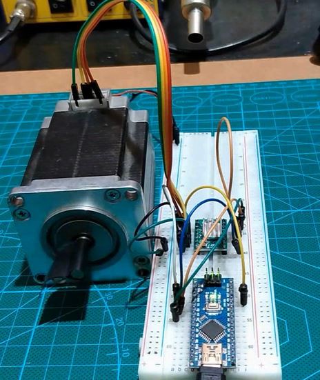
- Make the appropriate wiring diagram with an Arduino board.
- Write your first stepper control test.
- Start testing and debugging
Step 1: What Are the "stepper Motors"!
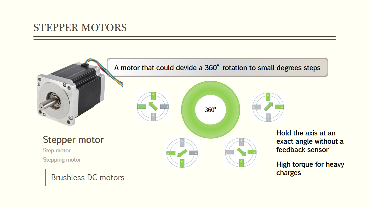
A stepper motor, also known as step motor or stepping motor belongs to the brushless DC electric motors with a specificity of dividing a full rotation into a number of equal steps or we better call them equal angles, the motor’s axis position can be controlled to move and hold at these angle without having a feedback sensor, and also due to its high torque capacity this kind of motors could maintain stable the motor axis on hold when it carries a heavy charge.

Talking about the two phase’s stepper motor category we have :
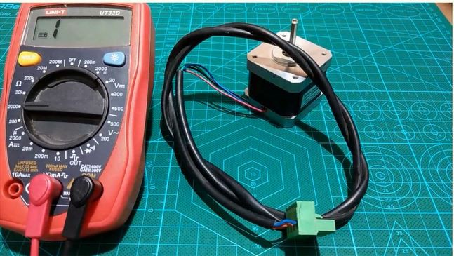
The bipolar motors
Comes with 4 wires to control the coils power polarity
Unipolar motors
That comes with 5 or 6 wires for the control.
Step 2: How the Stepper Motor Works
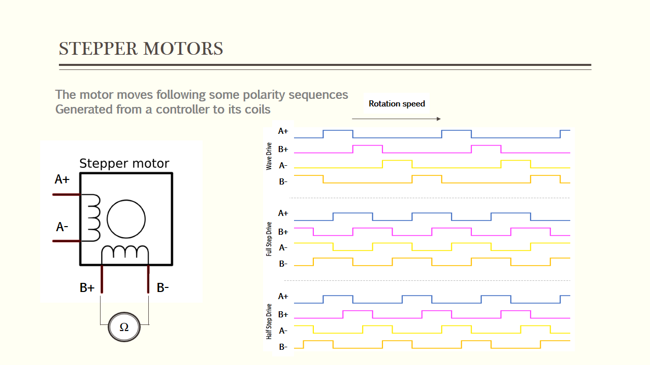
The coils are used to control the steps performed by the motor following some polarity sequences.
A typical driving pattern for a two coils bipolar stepper would be: A+ B+ A− B−
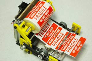
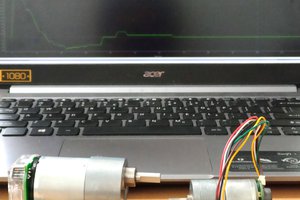
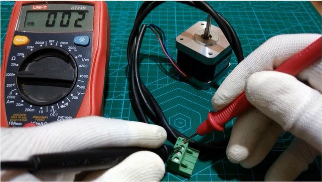
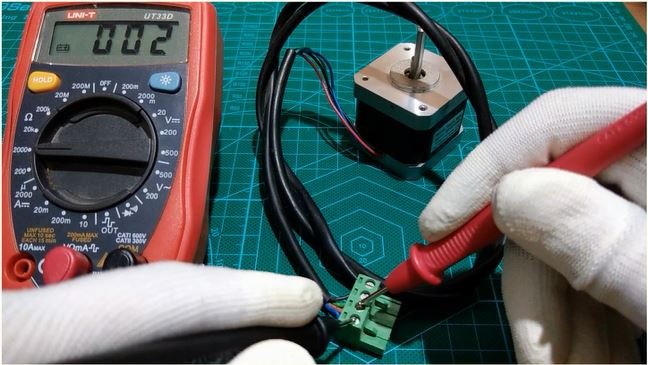
We can define the coils patterns using a millimeter by measuring the resistance between the stepper connection wires, and it should measure some resistance between each two coils ends, please check the photos above.
In order to make the stepper moves, a sequence of power polarity should be sent from a controller through the stepper driver and every time the sequence change the stepper perform a step in a precise direction with a constant speed which is the sequences speed so the faster the sequences move the faster the stepper rotate.
Step 3: The Stepper Driver A4988
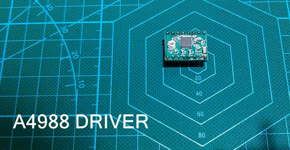
Backing to the control driver, basically some transistors to control the current flow through the stepper coils.
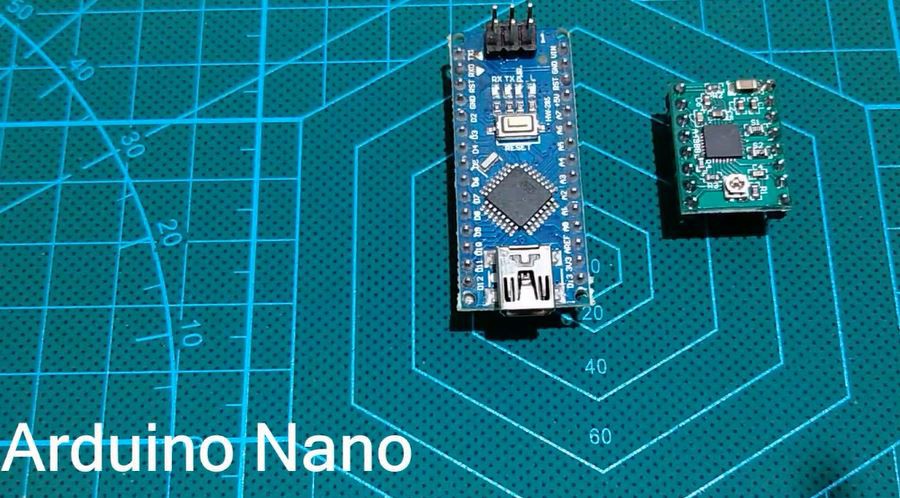
In our tutorial we will use the A4988 driver which allows us to easily control direction and speed of the stepper and could provide up to 35V 2Amps output control for the motor, the driver will be connected to an Arduino Nano board which is the heart of our control part.

Step 4: The Circuit Diagram
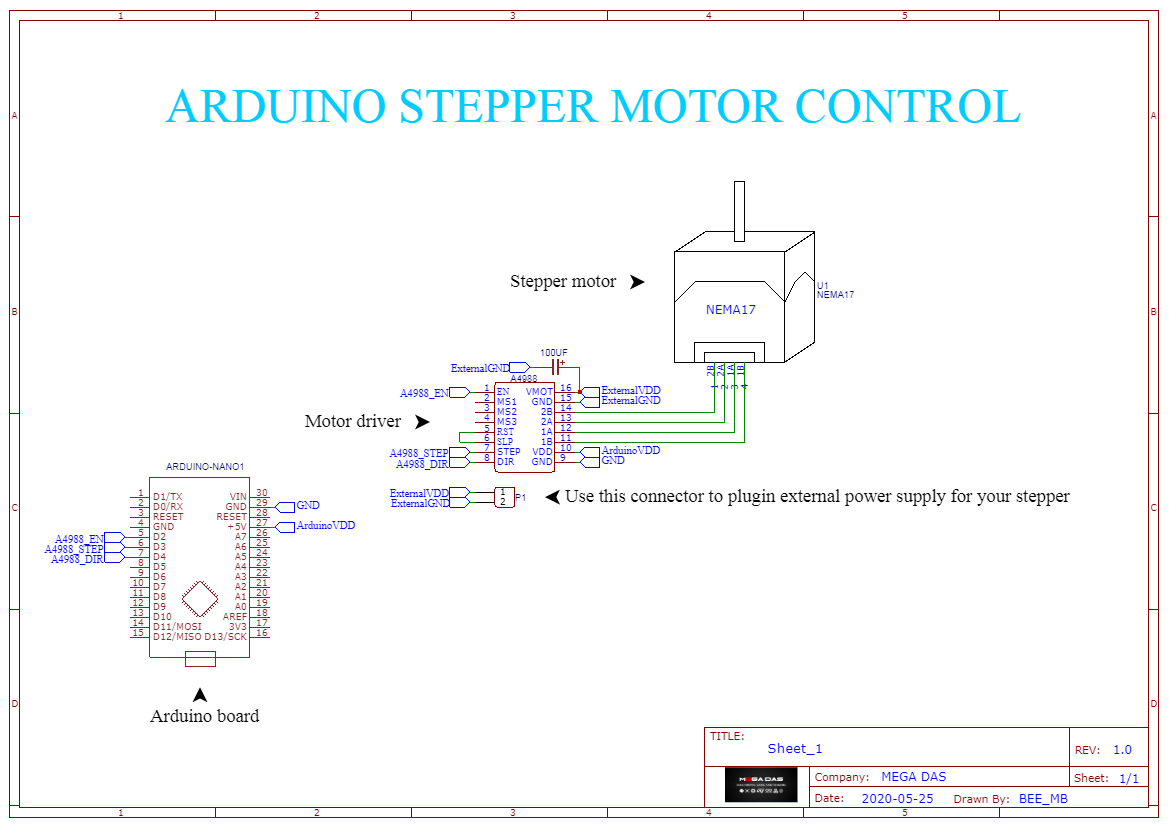
Moving the circuit diagram I used EasyEDA platform to create the above schematic (you can have it from the download link PDF Format), EasyEDA will help you to establish your circuit diagram easilly and then convert it in PCB due to its builtin features you can then place and order for your PCB from JLCPCB. by the way guys I invite you to join me in the new community HUB released by JLCPCB for makers in order to more engage the community.
★☆★ JOIN ME ON JLCPCB COMMUNITY HUB ★☆★Invitation link : https://www.hackster.io/jlcpcb/members/invitations?token=qUi9luLsdgqoeFgWov_ZAw
Backing to our circuit diagram as it shows the photo above we have the Arduino board connected to the stepper motor through the A4988 driver.
About the driver we will need three pins to connect to Arduino which are the Enable, the step and the direction pins.
About the driver output you will connect each pin the appropriate coil end. One important thing is connecting the sleep and...
Read more »
 Mrinnovative