 Brian Lough
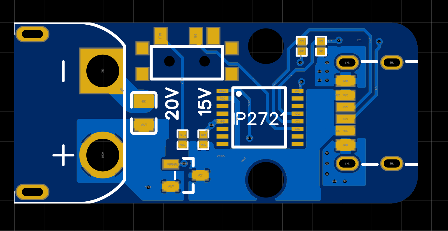
My first PCB design for this project was based on the IP2721, and I assembled this version on my stream this week. I'll go into more details about the IP2721 later in this update.
The stream is almost a perfect tutorial on how not to assemble things:
- I forgot to order a stencil
- I used solder paste that expired in Aug 2018
- My hands were very shaky for some reason
- It was my first time working with 0402. I wasn't using any magnification and I was kind of working around the camera for streaming.
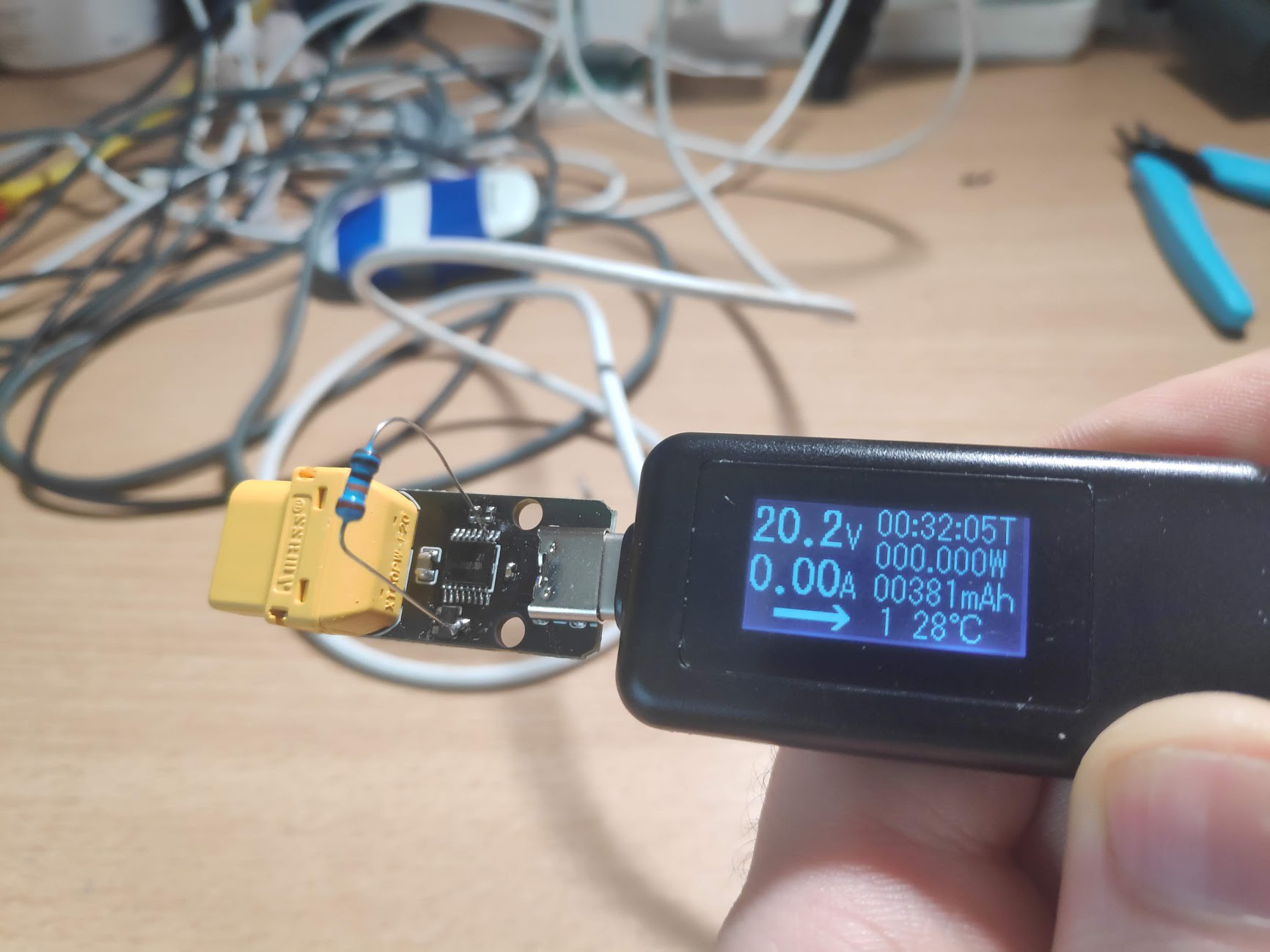
But all that said, we got it assembled, only to find it wasn't working as expected. It was negotiating 5V from the charger (or at least the charger was outputting 5V) rather than the 20V we expected it to.
One of the viewers on the stream mentioned that I was missing a 100k resistor between the "SEL" pin of the IP2721, the pin that dictates what voltage you want the IP2721 to request from the charger. I had it pulled high as per the data sheet, but I connected it to VCC directly.
So I lifted the IC, cut the trace to the SEL pin, leaving the SEL pin floating, which tells the IP2721 to request 15V. I reinstalled the IC, but it was still negotiating 5V. When I replaced the IP2721 we were in luck and it now negotiated 15V as expected. Also as expected, when we added the 100k resistor (as you can see in the photo) it negotiated 20V.
So a minor change and we'll be in business right? Well it's not that simple unfortunately ....
Why the IP2721?
What attracted me to the IP2721 was two things: @ $0.60 in low quantities it was extremely inexpensive but the most important thing for me was that it could be configured without programming it.
From a product point of view this would be very desirable because it really simplifies the process. This is a product I want to get assembled by a fab house, so keeping it simple keeps costs down an minimizes points of failure.
The only kind of a problem was that I could not find a source of the chips that I could buy myself. But I asked my contact in Makerfabs (who are more than likely going to be the place I get them assembled) could they get me some samples and they were able to.
Great, so whats wrong with it?
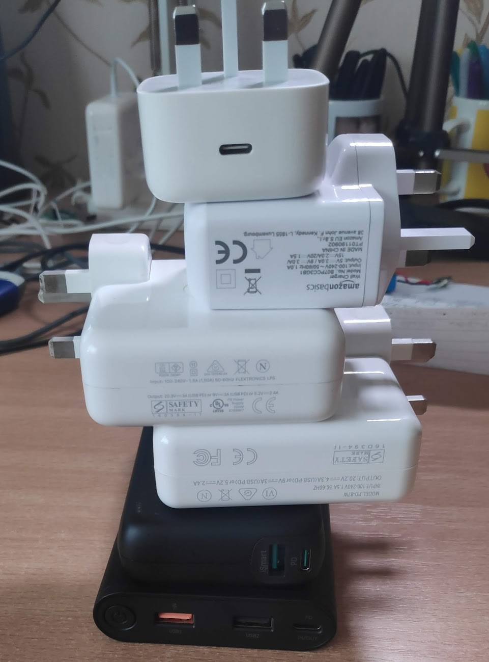
Basically there is certain chargers that are capable of working with the Ts100 that will not work with the board as pictured above. This was something I realized after I ordered the board. The problem is something you can figure out with the specs of the charger, but thanks to my Github sponsors I was able to buy a selection of chargers to test the reality (which was actually interesting)
Power Delivery supplies range in the watts the support, but also the voltages that they offer. The IP2721 will request the configured voltage from the PSU, but will fall back to next highest available.
Take for example this 30W supply:
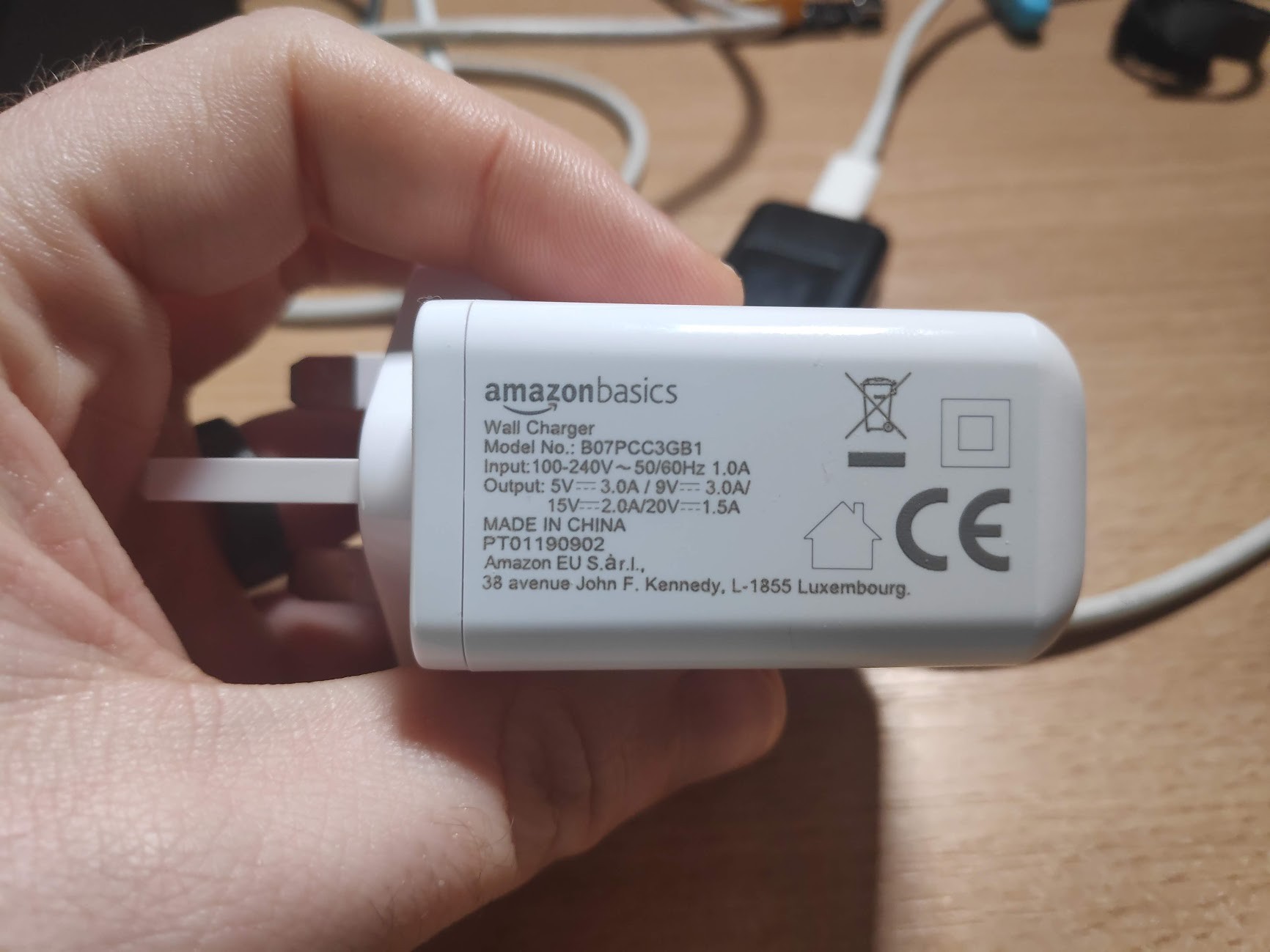
| Voltage | Chargers Max Current |
| 5V | 3A |
| 9V | 3A |
| 15V | 2A |
| 20V | 1.5A |
The TS100 is a fixed resistave load that works at voltage rage between 12-24V. The resistance in the heating element of the TS100 is 8.5 Ohms. If we apply Ohms law (Voltage = Current x Resistance) to for the voltages in the TS100 range, we get the following:
| Voltage | TS100 Current Requirement | Chargers Max Current |
| 15V | 1.76A | 2A |
| 20V | 2.35A | 1.5A |
Notice how the current requirement for the TS100 reduces with the reduction of voltage (This does have an impact on it's heat-up time). But as you can see from the above table, this PSU is not capable of powering the TS100 at 20V, but it is capable of powering it at 15V.
The issue is while PD does support checking the max current each voltage range can supply, the IP2721 does no do this. It's negotiation with the charger is based solely on the voltage range it supports.
So if you plug the Flex-C-Friend into this charger, it will negotiate 20V successfully, but when you try to power the iron it will trigger the PSU over-current protection and it will shut the TS100 off.
This is not a good situation as the PSU is capable of powering the TS100 at 15V. You could just insist everybody who wants to use this product uses a 48W or higher power supply, but one of the main draws of using PD at all is that you can use existing PSU for multiple purposes.
One possibility is to add a switch to the board to allow the user to configure the IP2721 for 15V, it was something I would have preferred to have avoided because I wanted to make this as simple a UX as possible for people, but I think it's worth trying out.
It's a sidewards mounted toggle switch pointed inwards to make it very difficult to change accidentally.
I am concerned about relying on the over current protection of peoples PD chargers though if they do not have the switch in the correct position.
Alternatives IC:
There are different ICs that do support the current checking, such as the STUSB4500. This allows you to upload voltage & current profiles, where if the charger can supply the voltage, but not enough current it will fall back to the next profile on the list.
The STUSB4500 is a much more expensive IC but the worst part of it for me is that the profiles need to be programmed via I2C, which really complicates the assembly process.
As part of the same stream I tested out a reference board for the STUSB4500 and it worked pretty much as expected. If you are interested in more details about the STUSB4500 I can do a separate log update on it, as this one has already taken me way longer than I expected it to!
The advantage of the STUSB4500 is that you will never get into a state where you hit the over current protection of the chargers, which seems like a nice things to me! I will more than likely still design up a board based on this, but I'm not certain if I will use stick with the IP2721 or move to this.
Testing - theory is not practice apparently!:
One thing I noticed that was quite unusual during testing is when I tested the IP2721 with a 45W power bank. The power bank, like the 30W charger above is out of spec for 20V (albeit much closer, it's rated for 2.25A, it needs 2.35A) but in practice it does successfully provide the required current to heat up the TS100 at 20V. When using the STUSB4500 it drops to 15V as it fails to match the 20V profile, which i thought was interesting!
Would love to hear your thoughts on any of this!
Brian
Discussions
Become a Hackaday.io Member
Create an account to leave a comment. Already have an account? Log In.
I'd honestly consider adding a super low cost uC to the board to allow basic monitoring/supervision and negotiation for the cases you mention, and in general to allow for an improved UX (allow user to select the voltage etc). Something like the STM8S001J3M3 would be ideal (and at 33 cents, it won't add significantly to the BOM.
Are you sure? yes | no
Do you know if the IP2716 is any different in the communication of the maximum output? I found another project with an Cypress CYPD3177 chip to do the same thing but sourcing it is a bit harder just like the STUSB4500(L).
Are you sure? yes | no