 Christian
Some thoughts
- Build a steampunk like clock with big (old) moving-coil instruments, but not with the help of a microcontroller.
- Clock source: Crystal? NE555? stepper!
- Count secs, mins, hours: binary counters with reset CD4040.
- Instruments: ebay-found two ELIMA 10V DC instruments.
- Drive the instruments: analog-digital-converter DAC0808.
- It should look really nice.
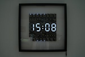
This is the result:
Implementation
Clock Source
In Germany, our mains voltage is 230V at 50Hz. Using a transformer and a capacity it is possible to drive a stepper. A 200 step stepper makes one revolution every second when driven by that circuitry.
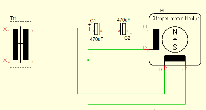
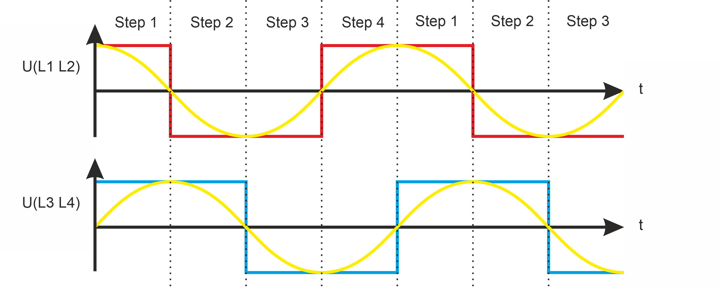
Why does that work? If you look how a unipolar stepper is driven (single step mode) you can see, that a 90° shifted sine wave fits perfect (some micro-step drivers for steppers use also an approximate sine wave).
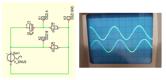
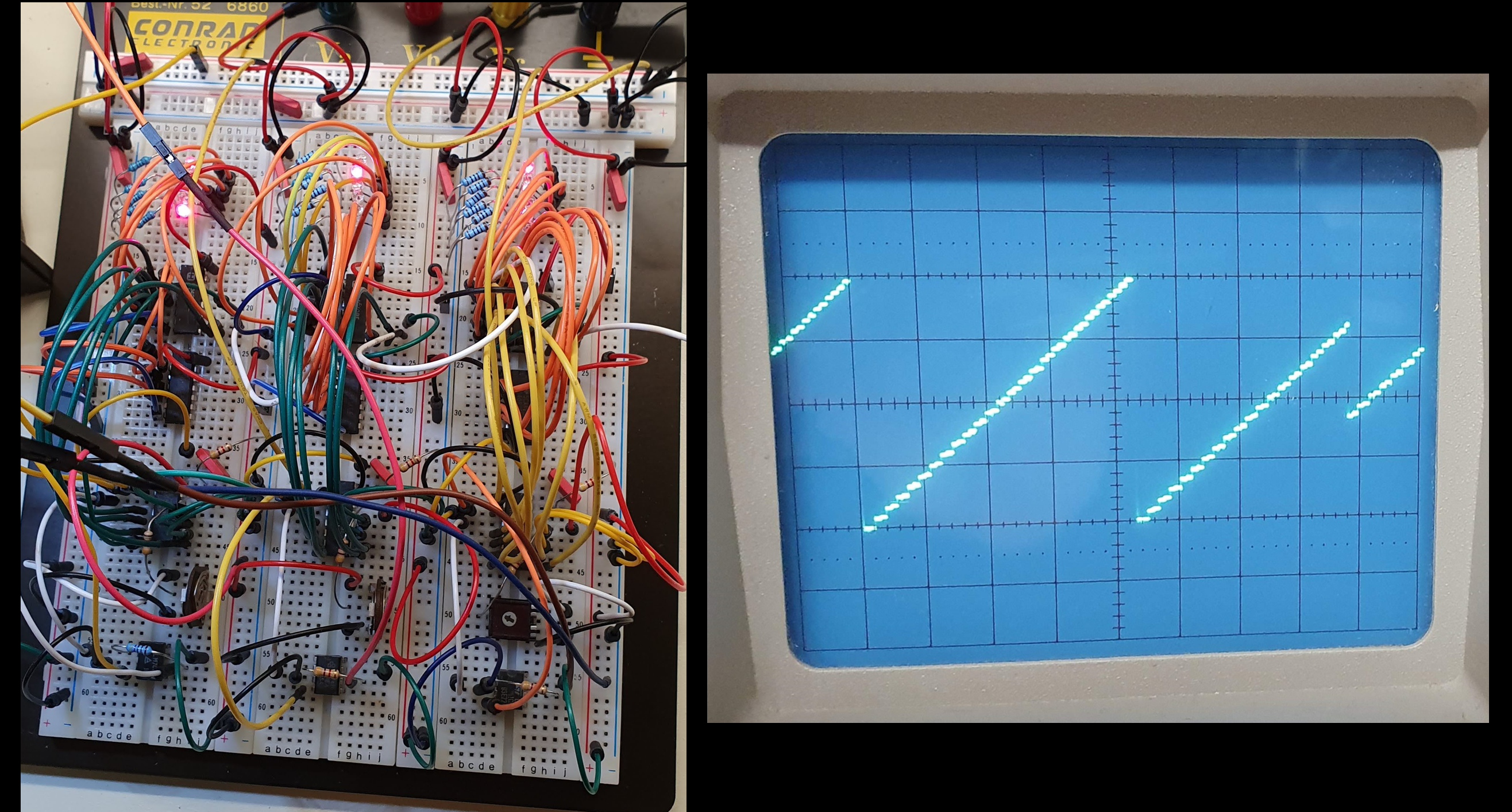
And if you put a capacitor in a circuit with a sine wave, the current runs 90° ahead compared the circuit without that capacitor. I tested this with the below circuit (the current is measured at the two 10Ohm resistors).
What is the correct value for the capacitor?
The impedance of the capacitors should be the same as resistance the of one coil in the motor at the desired frequency. The impedance is calculated as:
My motor has 30Ohm resistance. At 50Hz the capacitance must be 106uF. As I use 2 capacitors in series, the best match is 2*220uF resulting in 110uF. I measured the voltage at both coils of the stepper with the oscilloscope and it showed that the value is okay.
Because the stepper neds four steps for each cycle at 50 Hz and 200 steps for one revolution, one turn lasts exactly on second. On the axle of the stepper is a small 3D printed arm that breaks a light barrier. (ITR8102). This is used as the clock input for the seconds counter.
Counter
The CD4040 is a 12 bit counter.
- In: Clock (negative edge triggered)
- In: Reset (high active)
- Out: 12 buffered outputs
To divide/count up to e.g. 60 you have to trigger the reset at 0b111100. This can be done using diodes, a pull up resistor and a driver or, using an AND gate. I choose the AND gate because I also wanted some blinkenlights added and some tests showed that the diodes solution was not working so well in that case.
The CD4040 circuit (divide by 60), with AND gate and LEDs to show the bits:
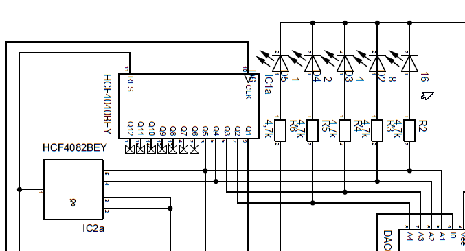
This circuit must be built for seconds (divide by 60), minutes (divide by 60) and hours (divide by 24).
The highest Bit is the clock input signal for the next stage. When the counter is reset, it falls from high to low and therefore triggers the next CD4040 clock input.
A small problem was: How can I set the time? The counter is falling edge triggered. My solution was a switch that disconnects CLK from the clock input and pulls the signal high. With a push button the CLK can then be pulled low. I also added a push button to reset the counter manually.
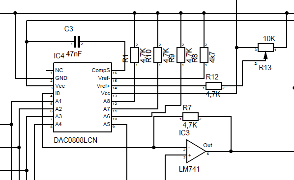
Digital Analog Converter
Here I used the DAC0808 with the default circuit from the datasheet. The not used lower bits were pulled down.
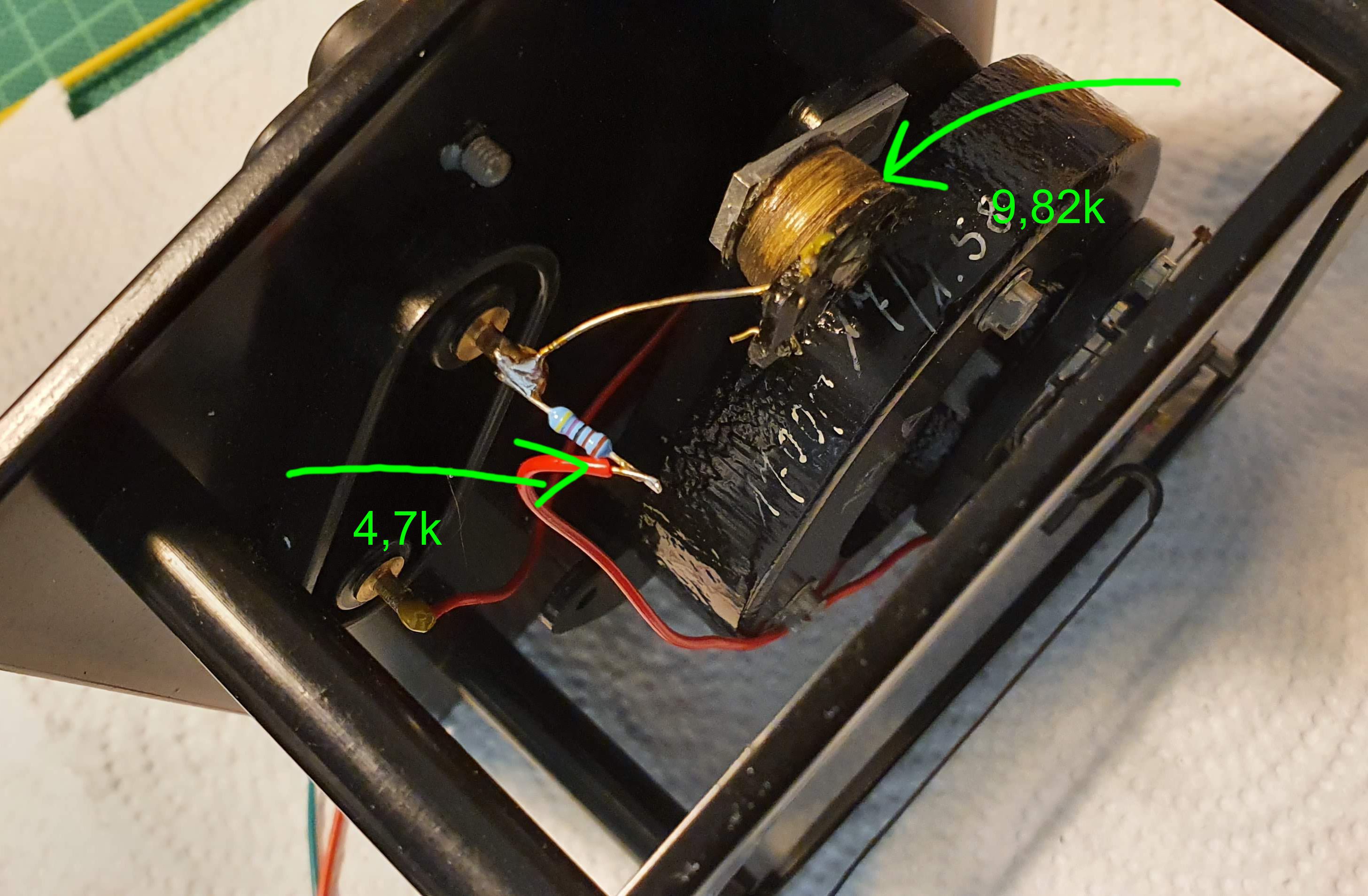
Moving Coil Instruments
I opened them up, cleaned them and painted them with shining black paint, also a new scale was be designed (with Corel Draw). I replaced the resistor in both instruments so that they work between 0 and 5V and not 0 and 10V.
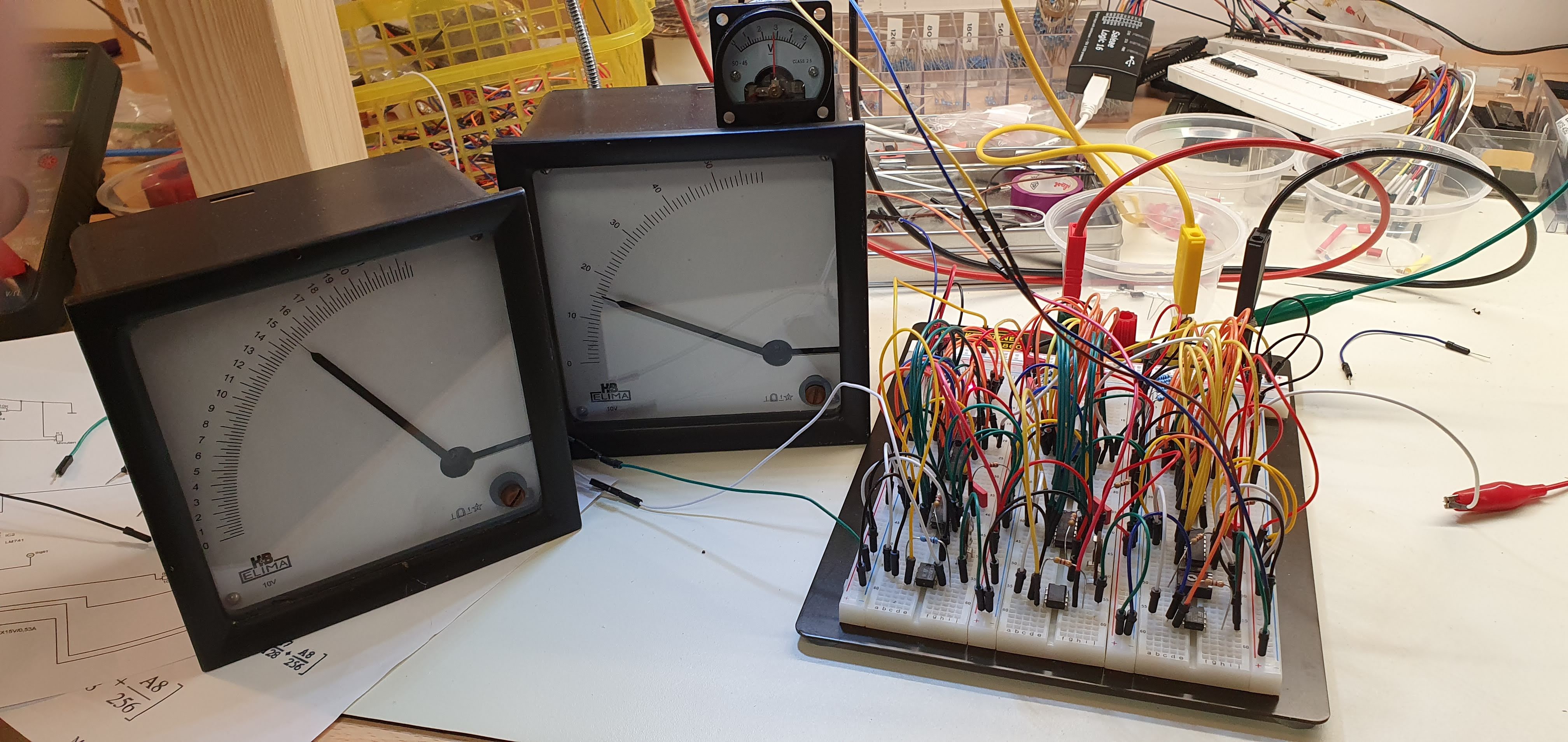
Putting it all together
The first test was on a bread board. Very impressive – but functional; for the clock source I used a function generator.
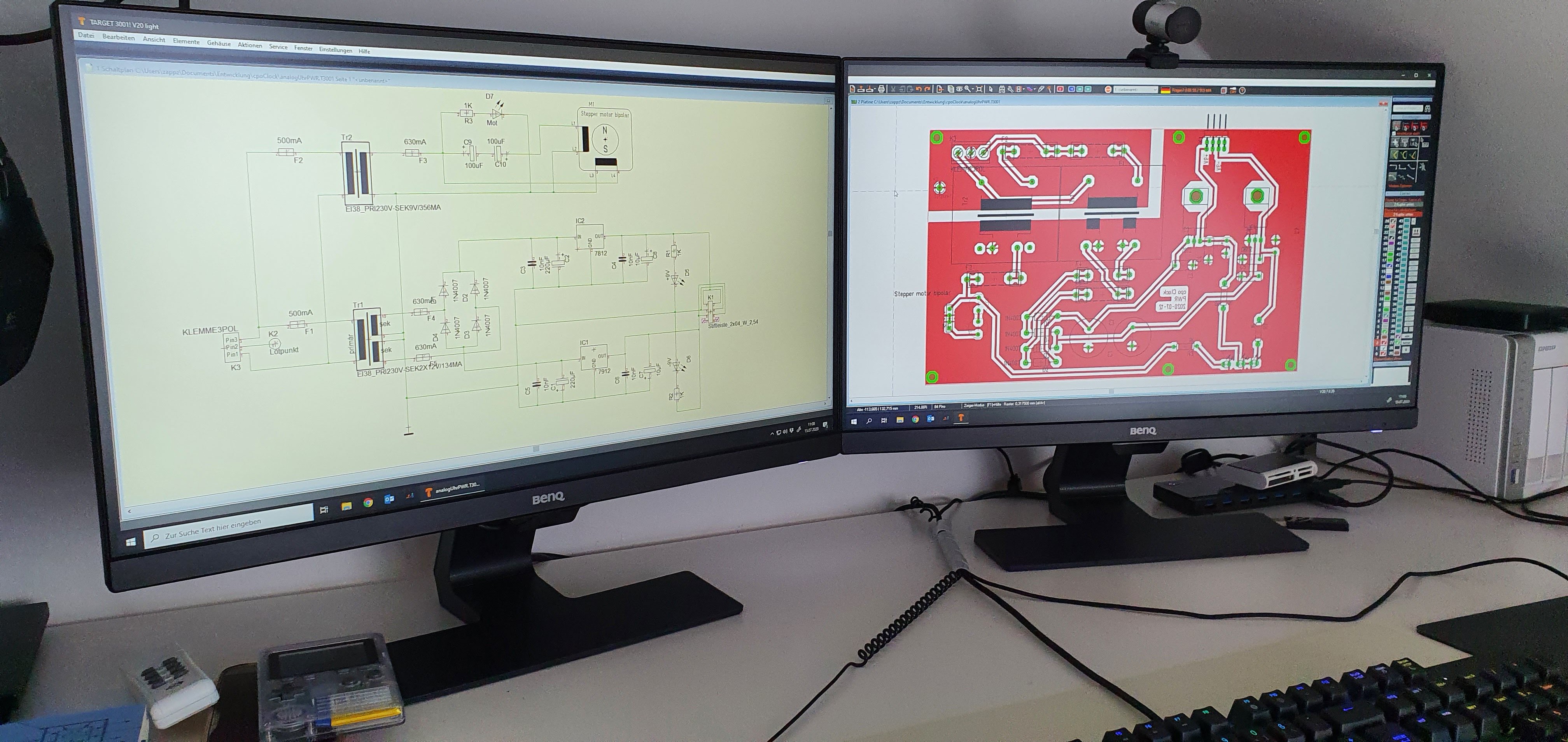
Next was designing the circuit boards. I designed 5 boards:
- Clock Source
- Seconds Counter
- Minutes Counter
- Hours counter
- Power source (=base plate)
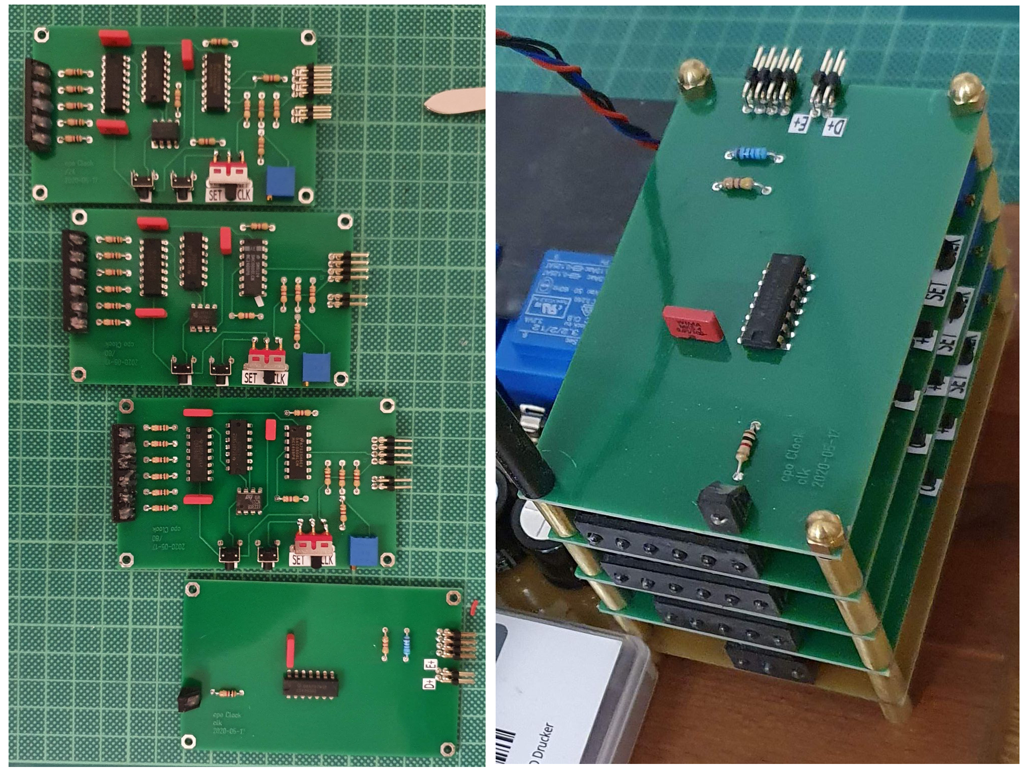
I printed mounts for the LEDs- The PCBs were stacked above each other with small brass spacers (with 3D printed core to center the M3 thread bars).
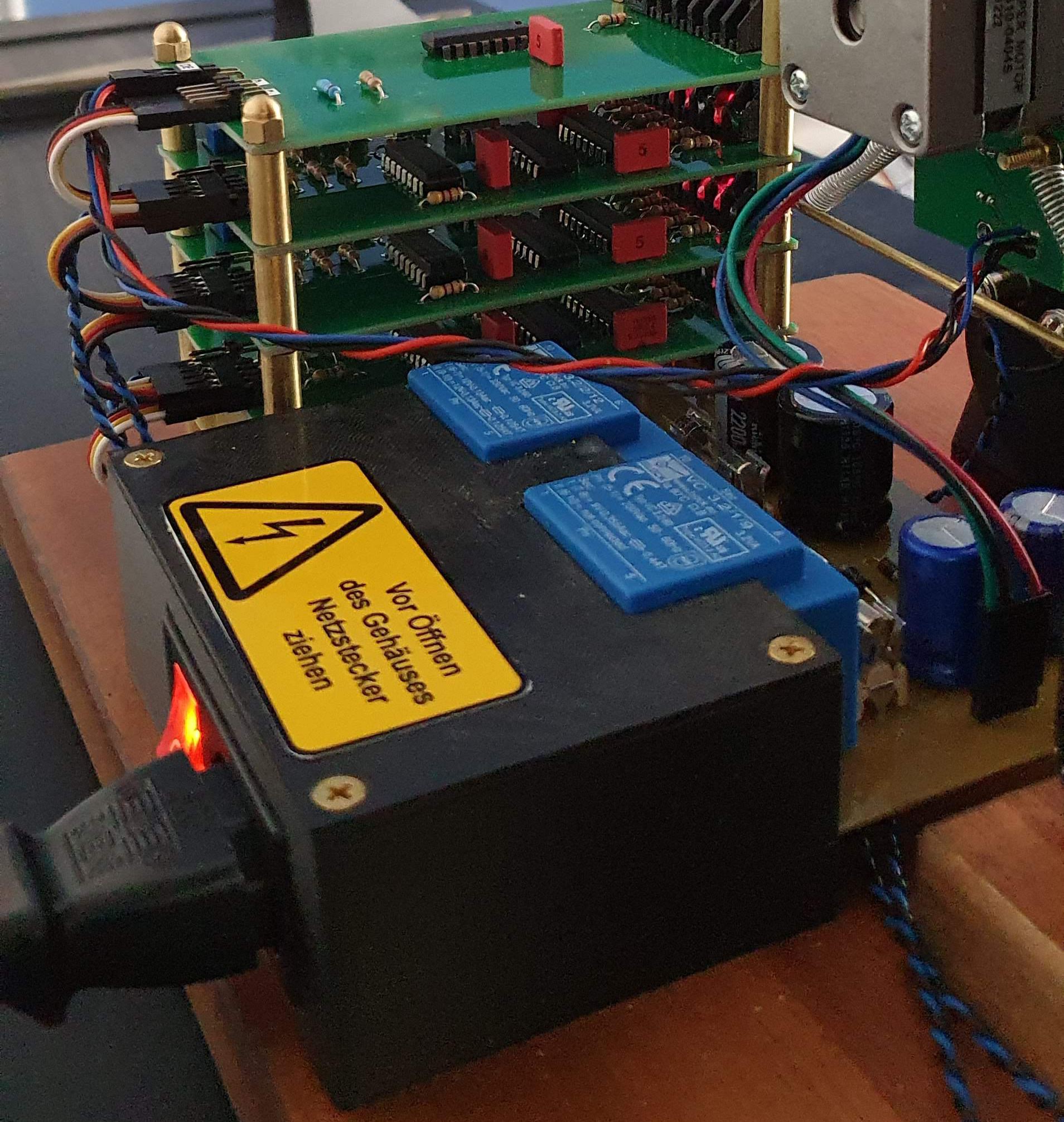
The next part was to secure the mains part (230V). As the the PCBs should all be visible, I only made a casing around the 230V part.
And the last challenge: The LOUD stepper…....
Read more »


 SwiftyTheFox001
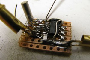
 rawe
rawe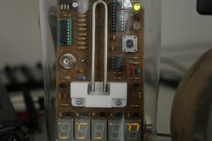
 Kris Slyka
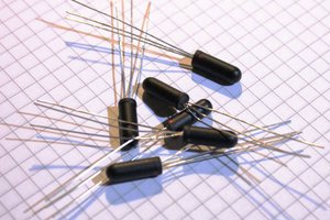
 Yann Guidon / YGDES
This is a beautiful and creative design. Thank you for sharing it! Do you have a video of it in operation?