Close
0%
0%

USBTinyISP to TPI adapter

Use your USBTinyISP/USBmicroISP to program ATTiny4/5/9/10s

Similar projects worth following
Starting from
$12.50
nsayer has 2293 orders / 162reviews
Ships from United States of America
I've started hacking around with the ATTiny9 of late. This is a microcontroller in a SOT23-6 package. It's pretty limited, but definitely has its place. Unfortunately, it uses a different programming methodology called TPI. TPI uses the !RESET pin and 2 of the GPIO pins for a sort of clocked async serial protocol not very different from PDI, but enough to be a different thing.

Fortunately, there's a patch to avrdude that can be used to do TPI, but it requires an external adapter to combine MOSI and MISO into the TPID signal. Additionally, if you disable the !RESET pin, then you invoke the TPI programming mode by injecting 12 volts into the !RESET pin.

This project is an adapter to accomplish both of these tasks.

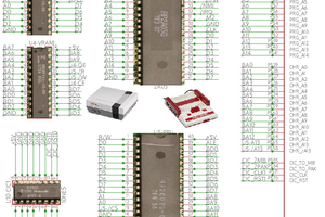
The primary concept at play is that you want to merge MOSI and MISO into a single combined TPID signal. The problem is that there's no mechanism to tri-state MOSI when it's the chip's turn to talk. So you connect TPID up to MISO and then connect MOSI to both through a series resistor. Select the resistor so that it's low enough to override any competing impedance on the target board, but not so low that it overrides the output signal from the chip and screws up programming. I've not worked out a value yet, but 330Ω seems a good starting guess.

Additionally, if you use the !RESET disable fuse, you can use the !RESET pin as a 4th general I/O pin. If you do, then to re-enter TPI, instead of driving that pin low, you feed it +12 volts. To do this conveniently, the adapter has a boost converter based on the AP3015 to turn the incoming 5 volt Vcc (TPI programming only works at +5 volts) into 12 volts, and then switch it onto the pin when the incoming !RESET is pulled low. This requires two MOSFETs - one P and one N. The N recognizes when the incoming !RESET pin is pulled down from 5 volts. That output pulls the gate of the P low, which actually switches the 12 volts in.

Because not all targets will be happy about having +12 volts injected, there's a switch on the board so you can select between the original active low !RESET signal and the +12 one.

If you are going to use the !RESET disable fuse, and support in-situ programming, you should insure that your design is tolerant of having +12 volts put there. The best way to do this is to put a reverse-biased diode between that pin (and the programming port) and your circuit, using it as an active-low signal with a pull-up on the other side. Of course when you start jumping through hoops like that, the ATTiny85 starts to look attractive.

The patch to AVRdude in the files section does three things:

  1. It adds TPI support to the USBTinyISP programmer (this part of the patch is courtesy of David Mosberger).
  2. It adds Linux SPI support (this part of the patch is courtesy Kevin Cuzner).
  3. It adds TPI support to the LinuxSPI driver (that's my work, though I took some cues from David's work).
  4. It cleans up everything relative to avrdude-6.3 and fixes a bug or two (again, me).

plain - 30.49 kB - 07/08/2020 at 23:44

Download

Adobe Portable Document Format - 18.53 kB - 07/08/2020 at 23:44

Preview
Download

sch - 153.83 kB - 07/08/2020 at 23:45

Download

brd - 46.41 kB - 07/08/2020 at 23:45

Download

  • Design progress

    Nick Sayer06/24/2020 at 22:55 0 comments

    I was able to hack the prototype to insert an N MOSFET between the two Ps and now the behavior of the HV !RESET jumper is correct. It's effectively floating normally, and then has 12 volts switched onto it when the incoming !RESET line is pulled low.

    I've also validated that it actually works properly with a real device. I've turned the RSTDSBL fuse on and off several times in a row, verifying that programming doesn't work with the fuse on and the adapter's jumper in the NORM position.

    So the boards I've already ordered from OSHPark will work correctly.

    For my own part, I intend to just leave the jumper on HV permanently. This does behove you to insure you don't attach the programmer backwards - that would impose 12 volts on Vcc for the duration of the programming attempt, though ground would be hooked to TPID, so that may not be completely tragic.

    As soon as I build the next board, this will be added to Tindie.

  • linuxspi support too!

    Nick Sayer06/23/2020 at 06:42 0 comments

    I made a mashup of the USBTinyISP TPI patch and the linuxspi driver for avrdude. So now linuxspi can do TPI stuff as well now.

    This integrates perfectly with my Raspberry Pi AVR ISP cap, which does level shifting and target power insertion for the Raspberry Pi to act as an AVR ISP programmer. But with the hack on linuxspi and this adapter, it can now do TPI programming as well!

  • Patching AVRdude

    Nick Sayer06/23/2020 at 04:49 0 comments

    The patch for avrdude to add TPI support to the USBTiny was posted to the AVRdude mailing list a few years ago here. That patch is what's in the files section here. It doesn't apply cleanly to avrdude 6.3, but the one .rej file is pretty easy to just do by hand (it's inserting an include for tpi.h into usbtiny.c).

    It turns out that's not the only issue.

    A chip erase won't reset the fuses in the config section. To do that, you must perform a SECTION_ERASE operation on the config block before performing a write. There's code in avr.c to do this in the function avr_write_byte_default(), but it turns out that that function isn't called when you try to write the fuses on the tiny9. Instead, the method called is avr_write(). So that little block of code that checks whether you're writing the "fuse" memory section or not needs to be copied (and adapted slightly) into that other function.

    I'll go fetch a clean source tree of 6.3 and make a new patch that incorporates both of these changes. With that done, you should be able to freely clear and set the RSTDSBL fuse and use the HV jumper position when it's cleared to engage TPI.

  • First build report

    Nick Sayer06/23/2020 at 00:08 0 comments

    The first build was an almost perfect success, but there is one error that must be corrected.

    If you jumper the board for the "normal" !RESET line, it works perfectly. Merging MOSI onto TPID through a 330Ω resistor works just fine. Whether it still works on the AC Safety Timer board that has a significant impedance on TPID remains to be seen, but it's functional nonetheless.

    The boost converter works correctly and does generate 12 volts from the incoming 5, but unfortunately, the switching circuit to shunt it onto !RESET just presents the 12 volts constantly. The issue is that I neglected the body diode in the "bottom" MOSFET (the one that sends 5 volts out when the ISP !RESET line is pulled low. The body diode will always see the 12 volt pull-up on the second MOSFET and conduct from that 12 volts down to 5, pulling the second gate low(er).

    All that said, you can program a Tiny9 with the RSTDSBL fuse set to 0 with the programmer as it is now. You just have to plunge the pogo pin adapter onto the board and press RETURN on the avrdude command line relatively quickly.

    The fix is to introduce an N channel MOSFET in-between. Unfortunately, there's no option to use just 2 MOSFETs for this switching arrangement. We need to detect a low input, which requires a P MOSFET, and we need to isolate that with another MOSFET that can detect the high output from that and bring the final MOSFET gate low. That's an N MOSFET. So there has to be 3.

    But despite all that, the result ought to work just fine. Now I just have to wait for boards and then it can go into the Tindie store.

View all 4 project logs

Enjoy this project?

Share

Discussions

Similar Projects

Does this project spark your interest?

Become a member to follow this project and never miss any updates