 Fabian
UPDATE:
i started the development and build of a new version of WinDIY. I will post more information in a new project log and on my Instagram.
You can find more infos here:
- https://www.instagram.com/nerdiy.de/
- https://hackaday.io/project/184849-windiy2-horizontal-axis-wind-turbine
- https://nerdiy.de/en/news-mai-2021-aktuelle-projekte-und-entwicklungen/
I hope to see you there :)

Brief overview of what this is about:
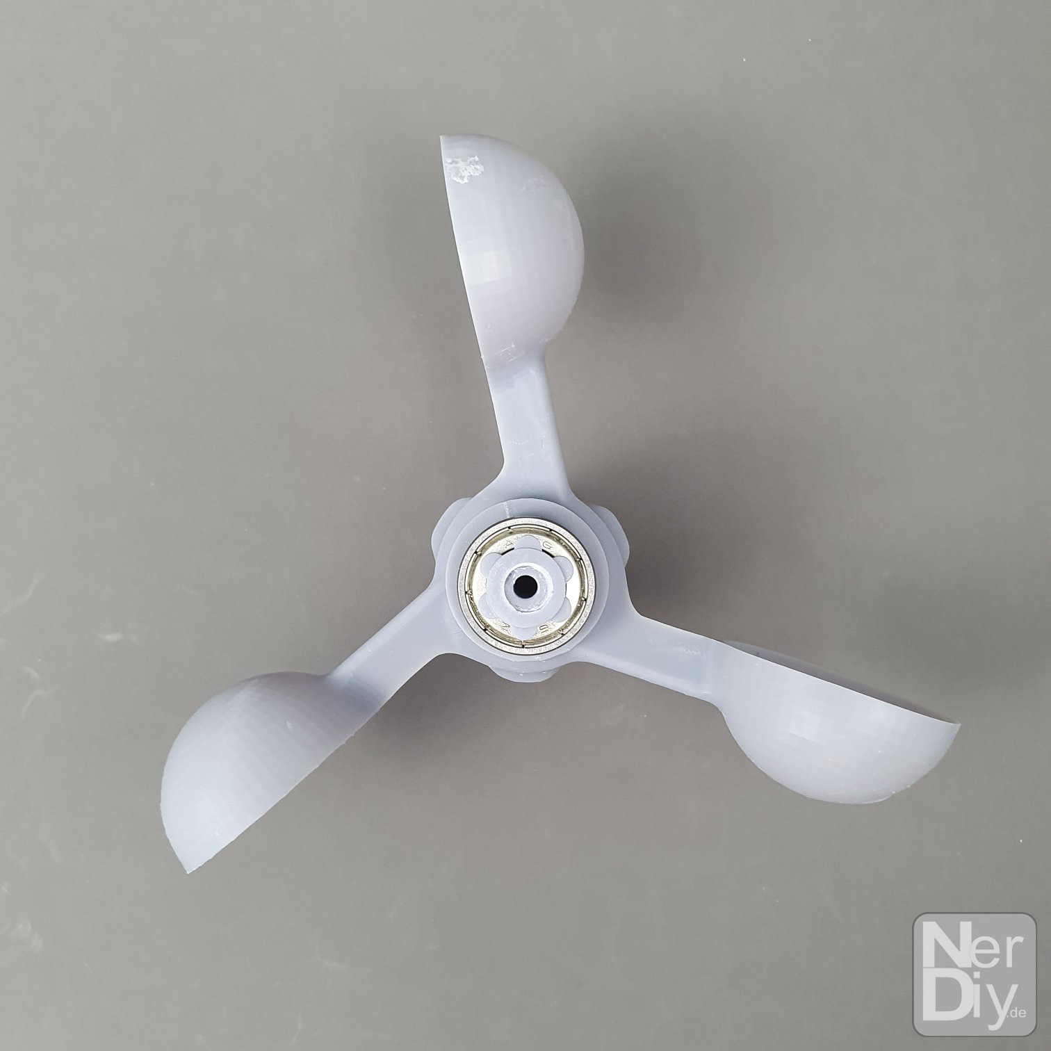
- Wind turbine build from 3D printed parts
- HAWT design
- Rotor diameters from 0.5 to 1.2m possible
- 3D printed wings
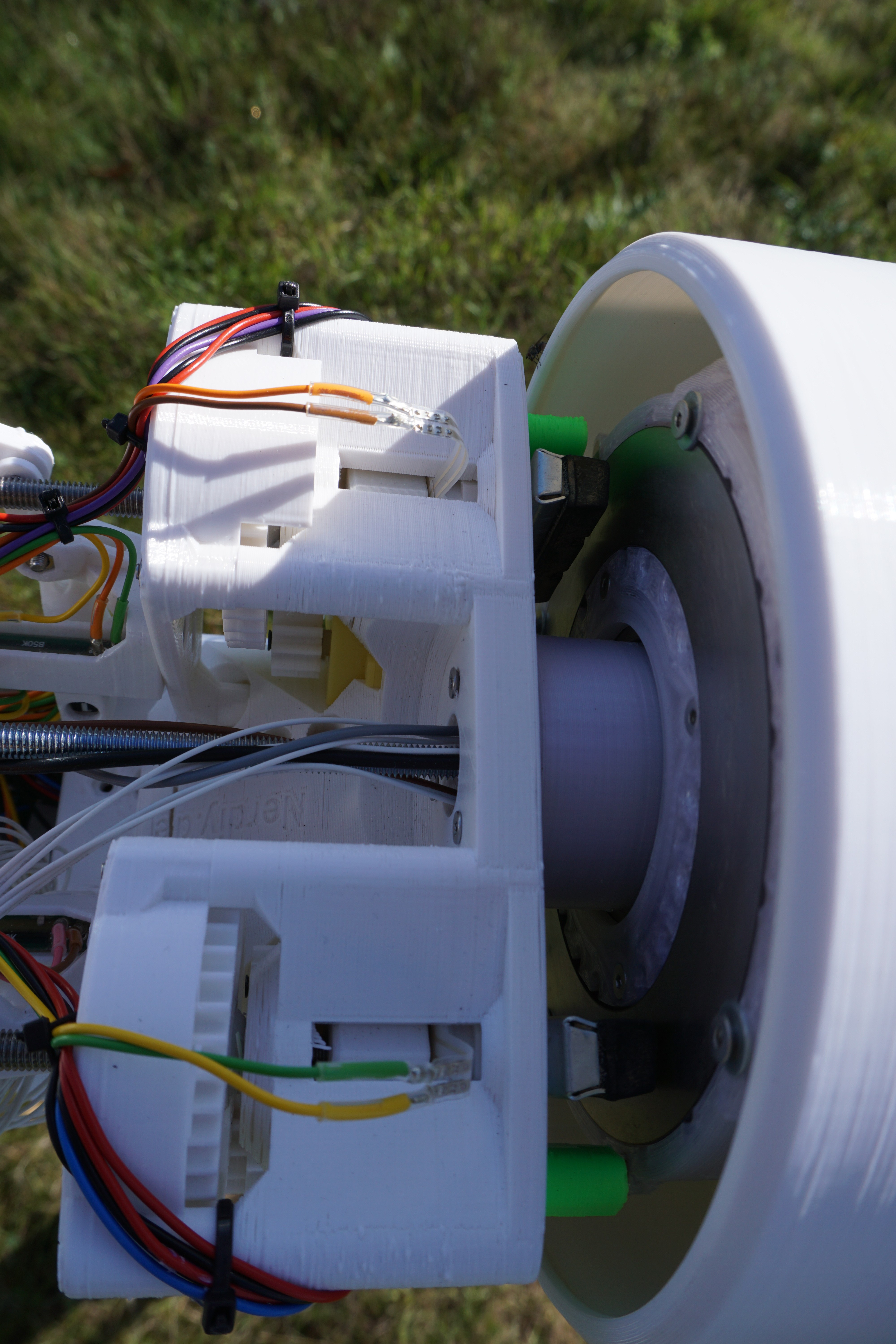
- Uses a 3D printed disk generator for energy generation
- Safety functions through active pitch adjustment of the wings, mechanical brake and electronic brake function via the disk generator
- Can be printed using any "normal" (20x20cm bed size) FDM Printer
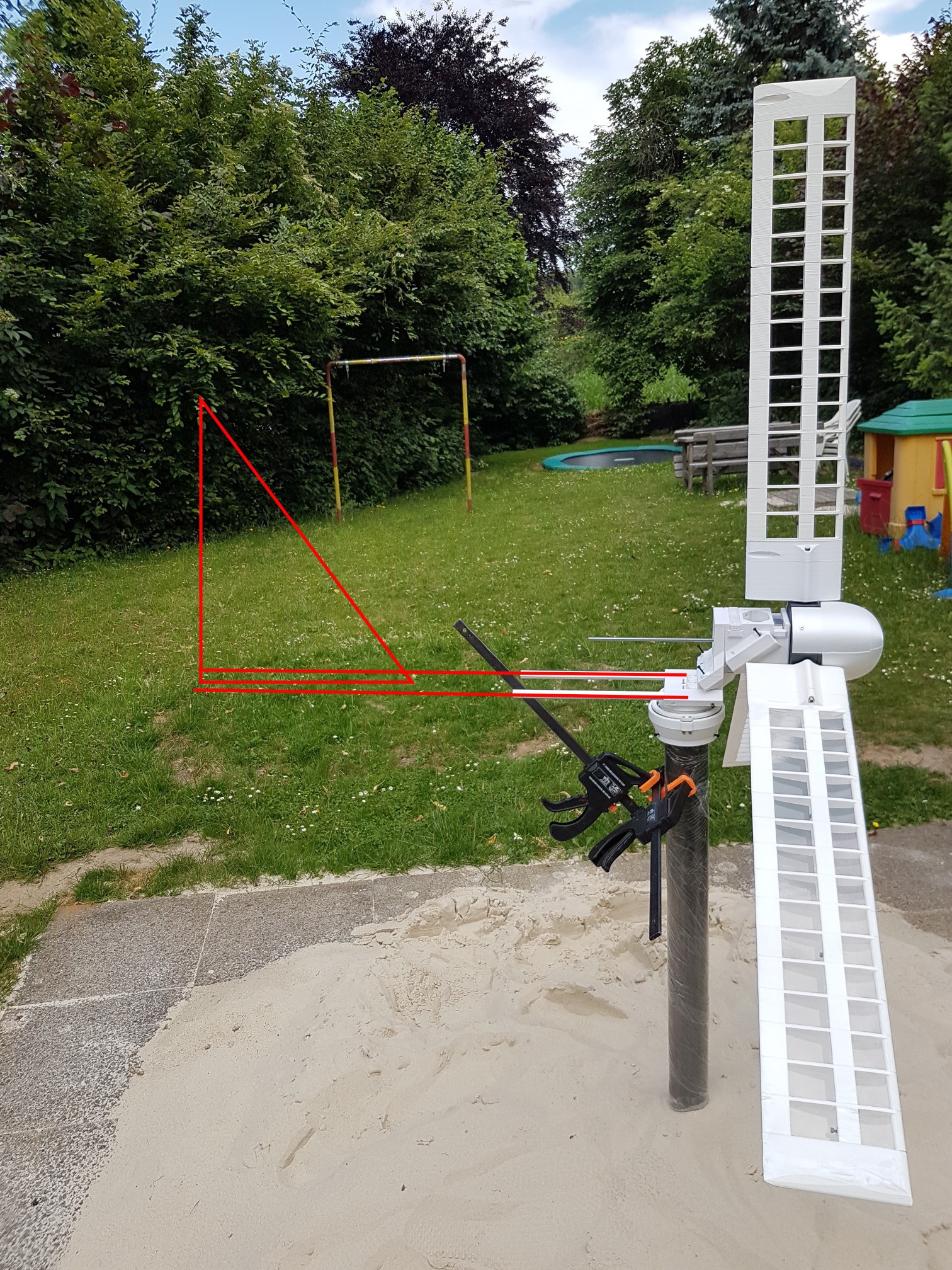
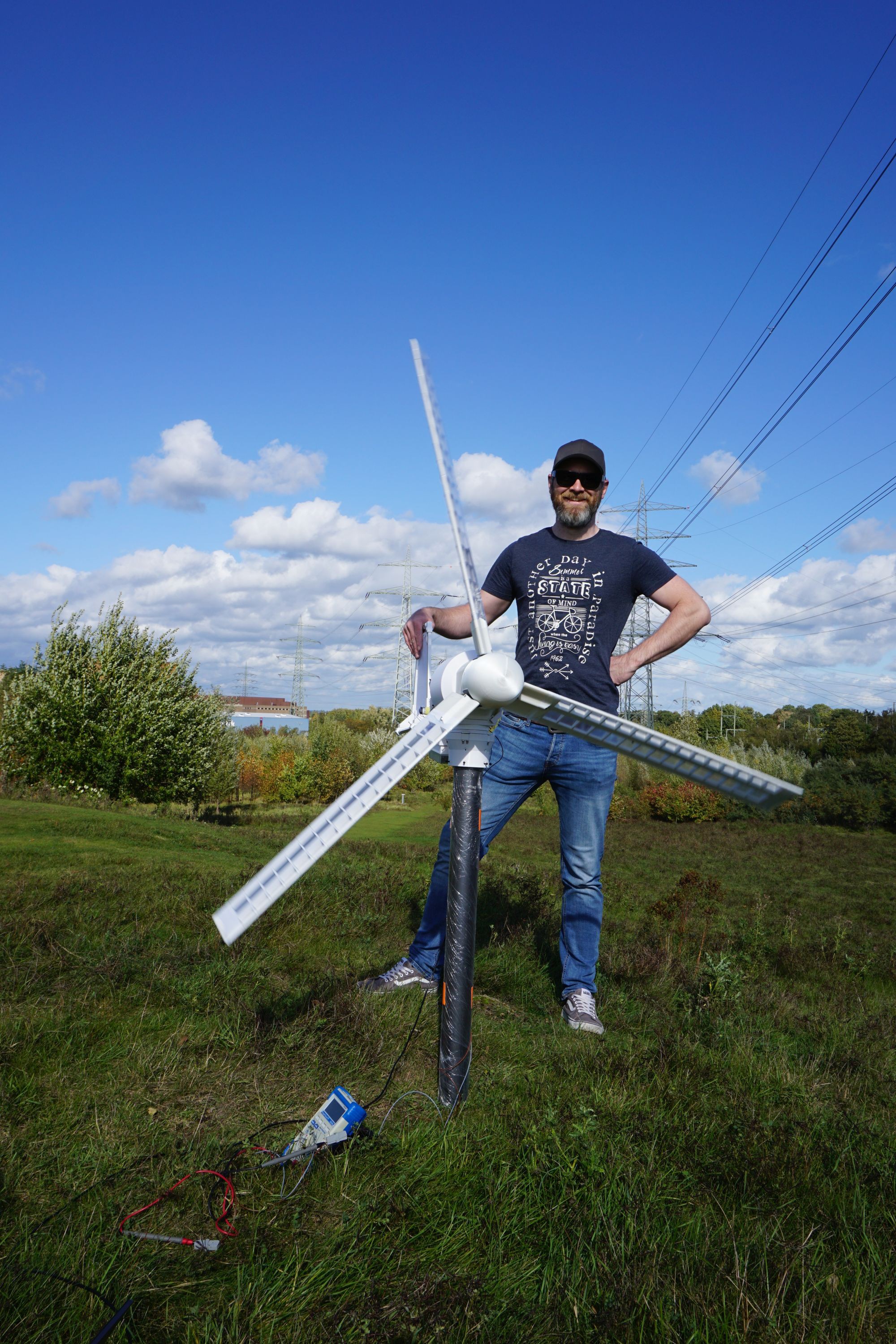
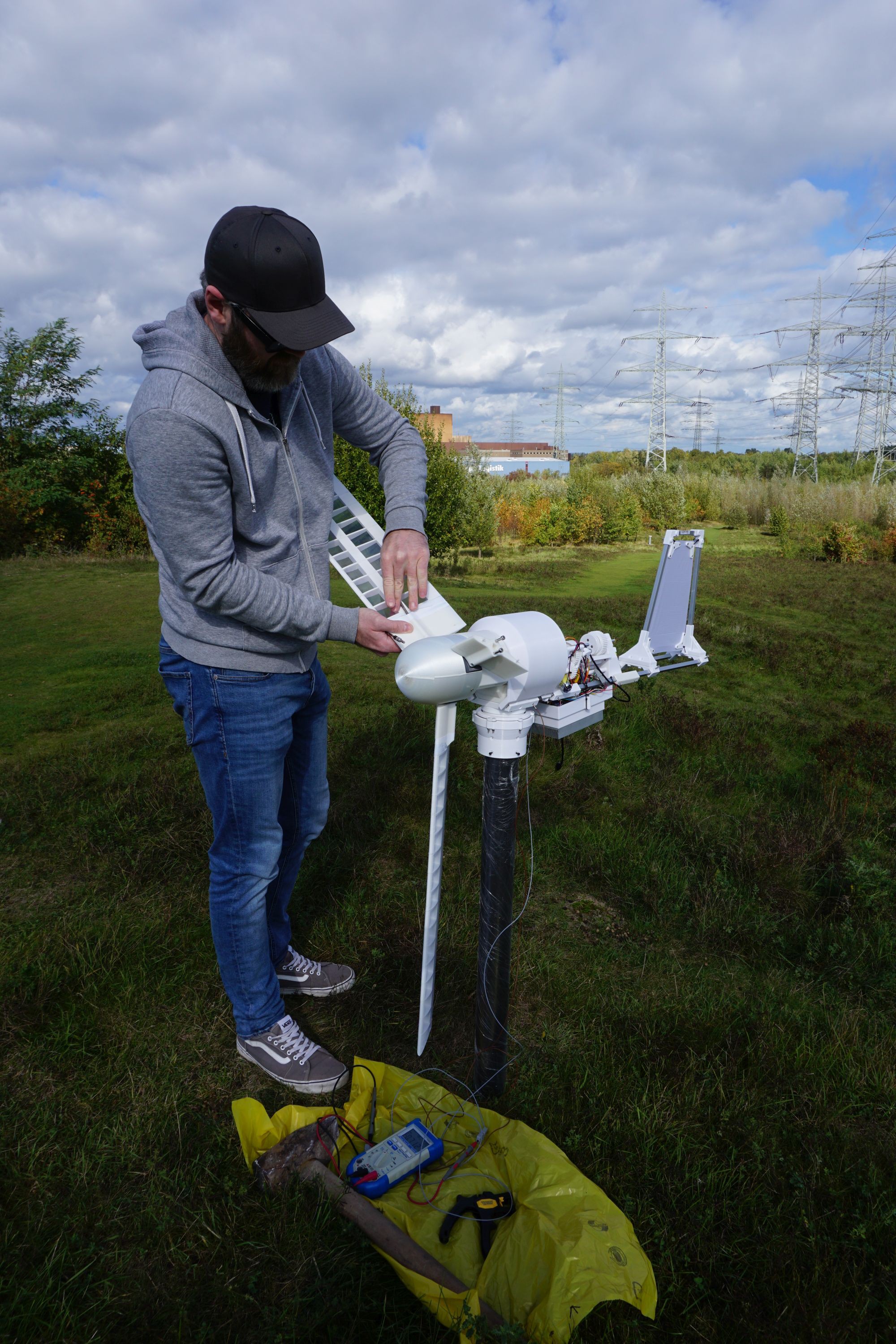
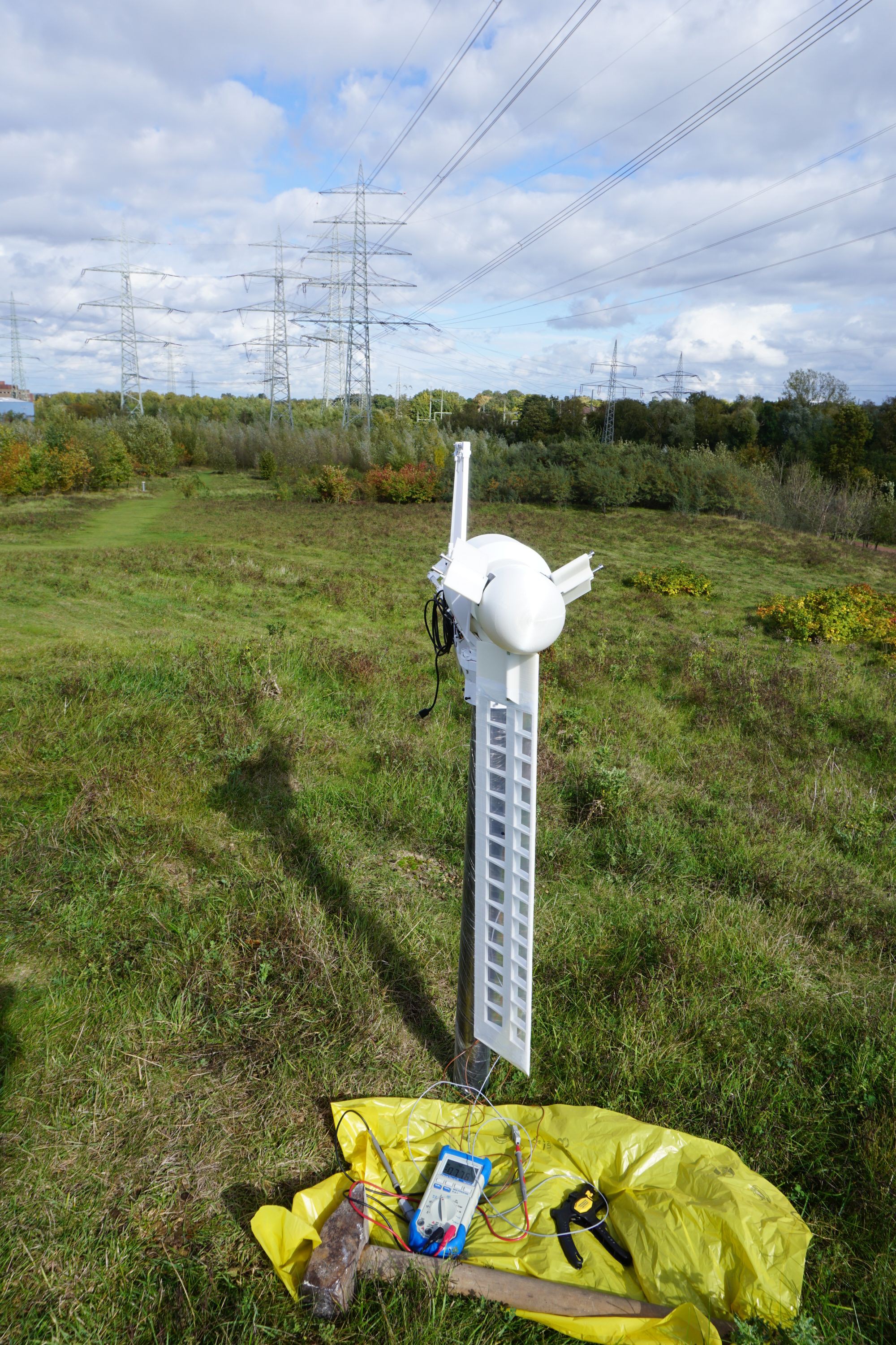
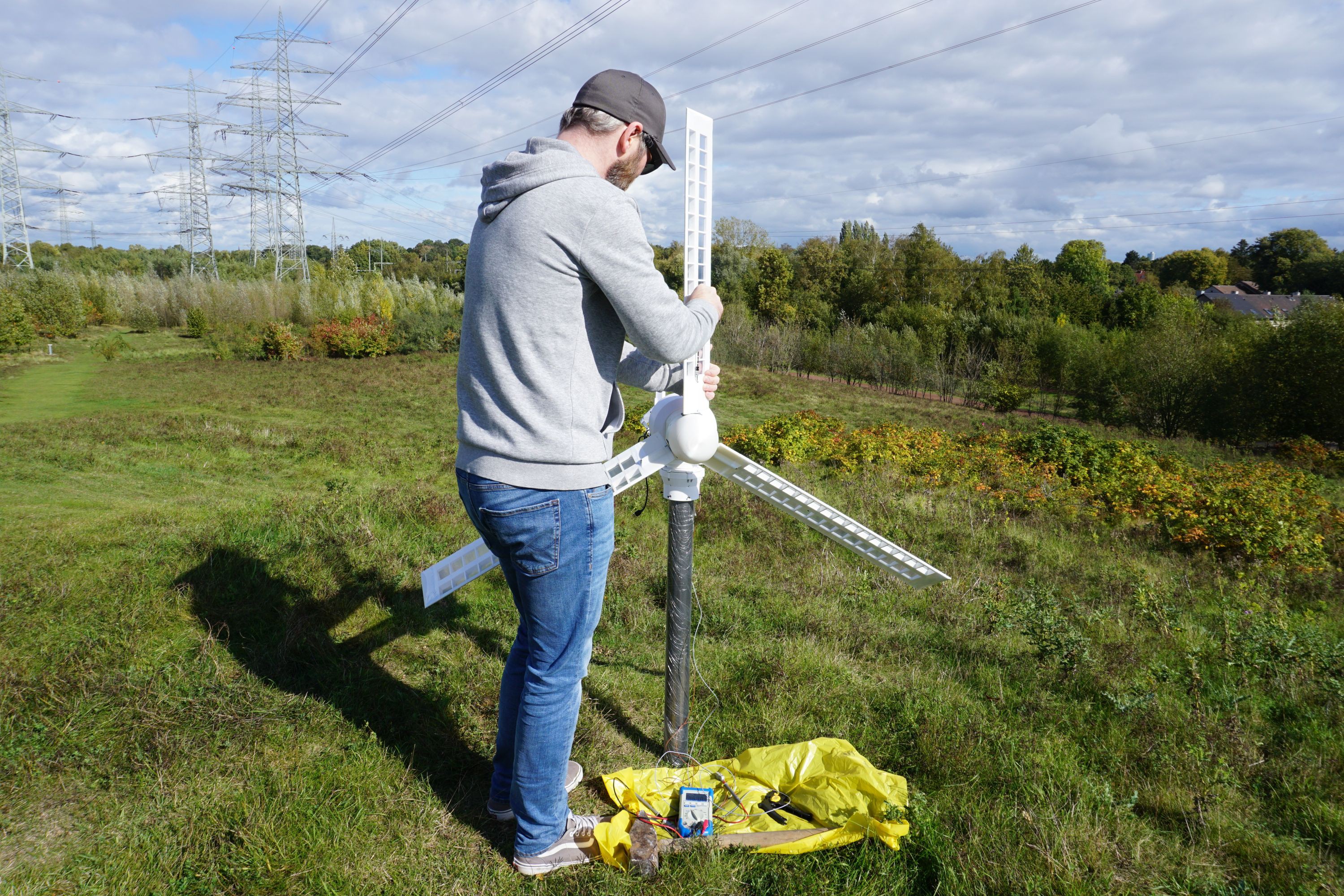
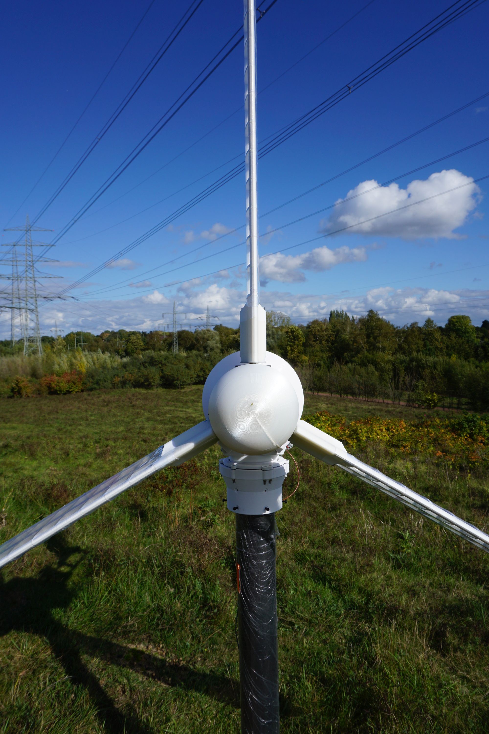
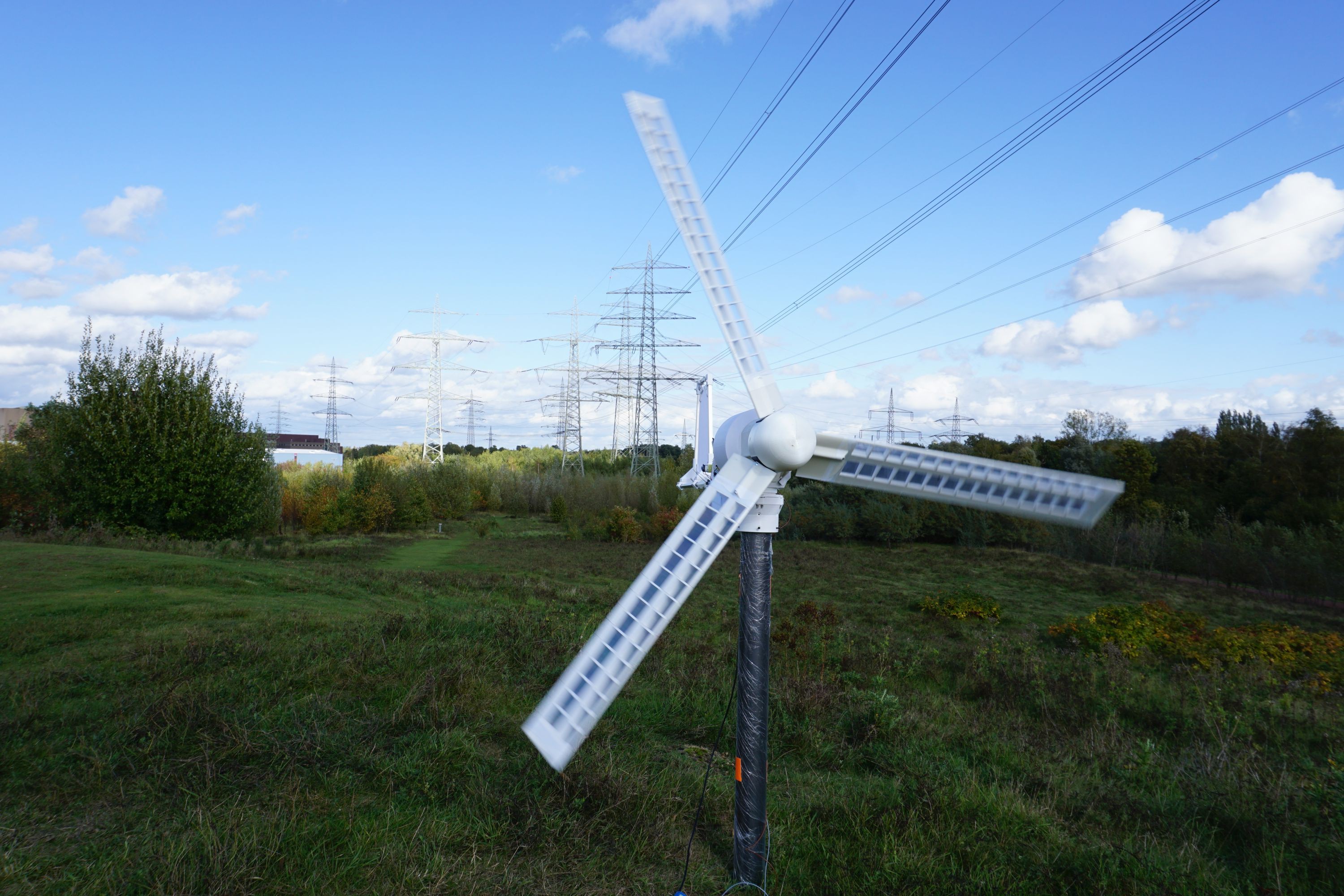
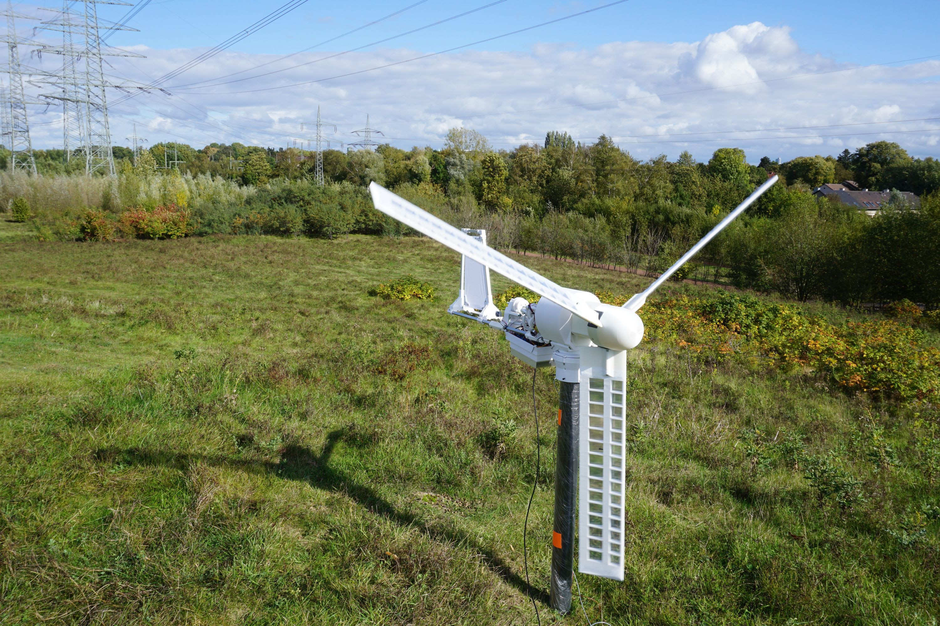
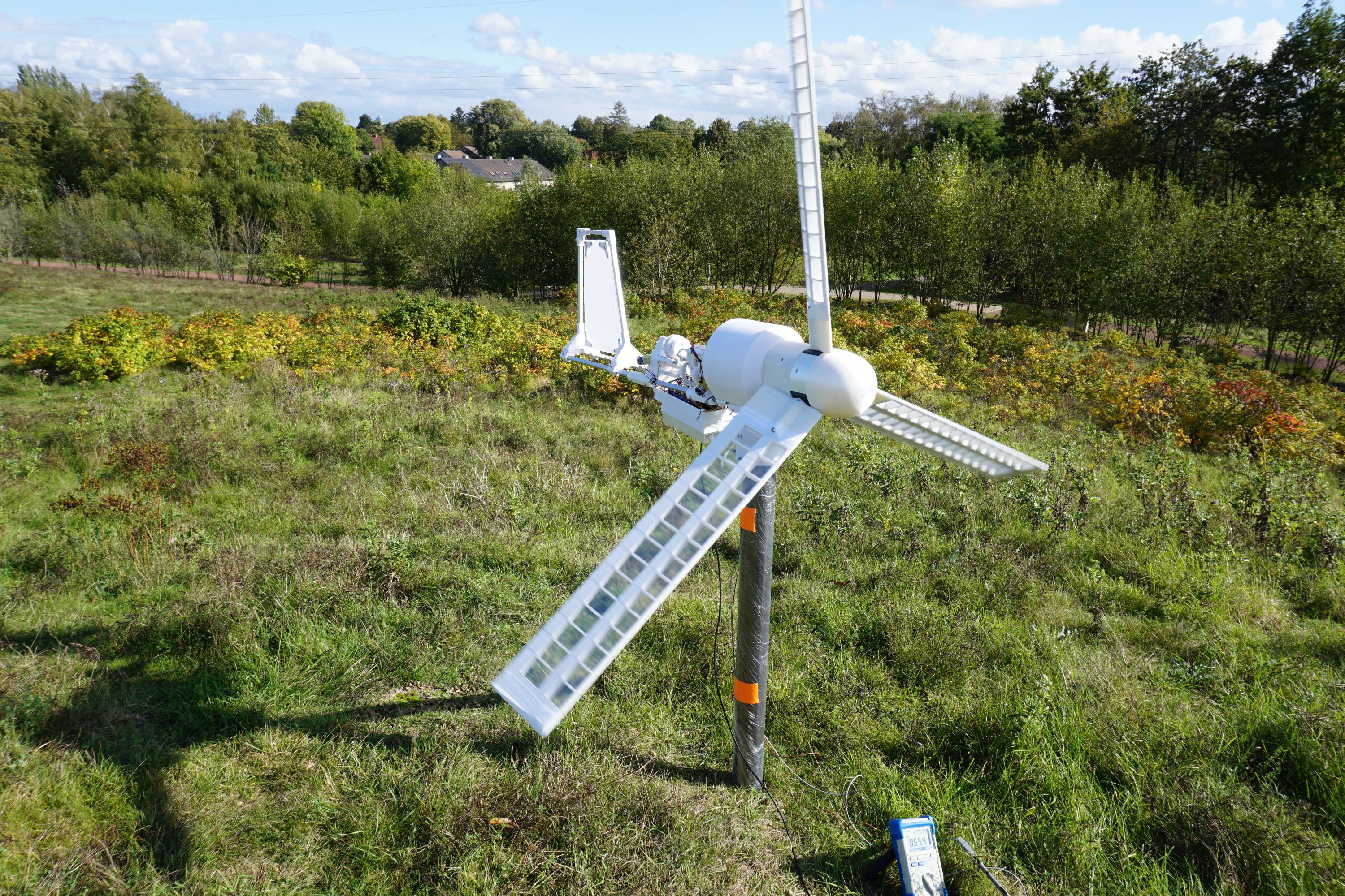
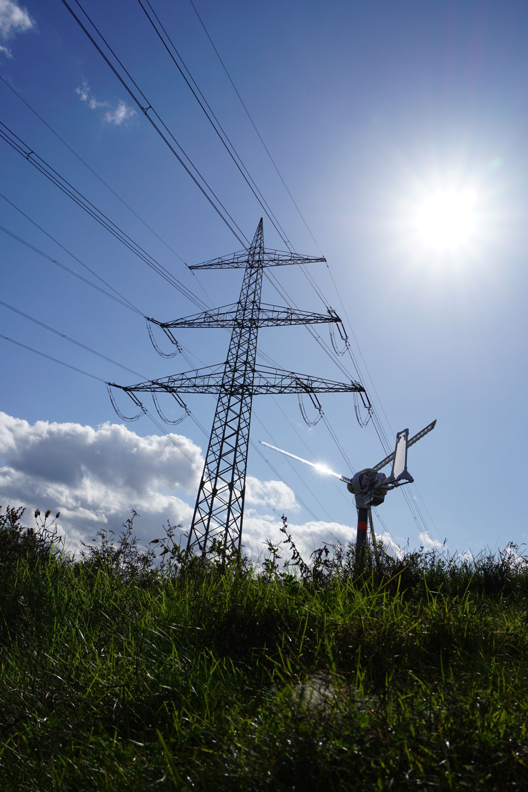
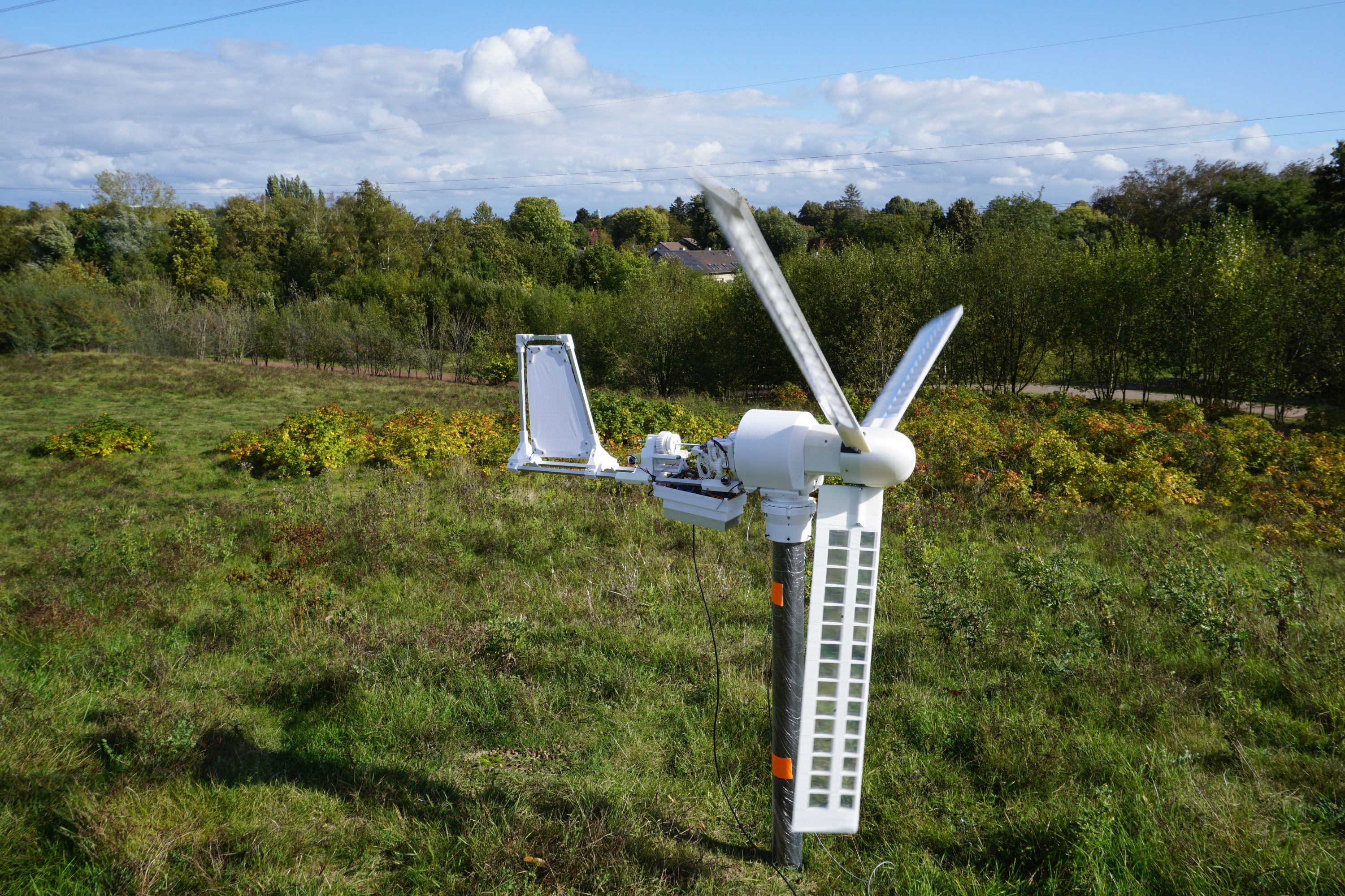
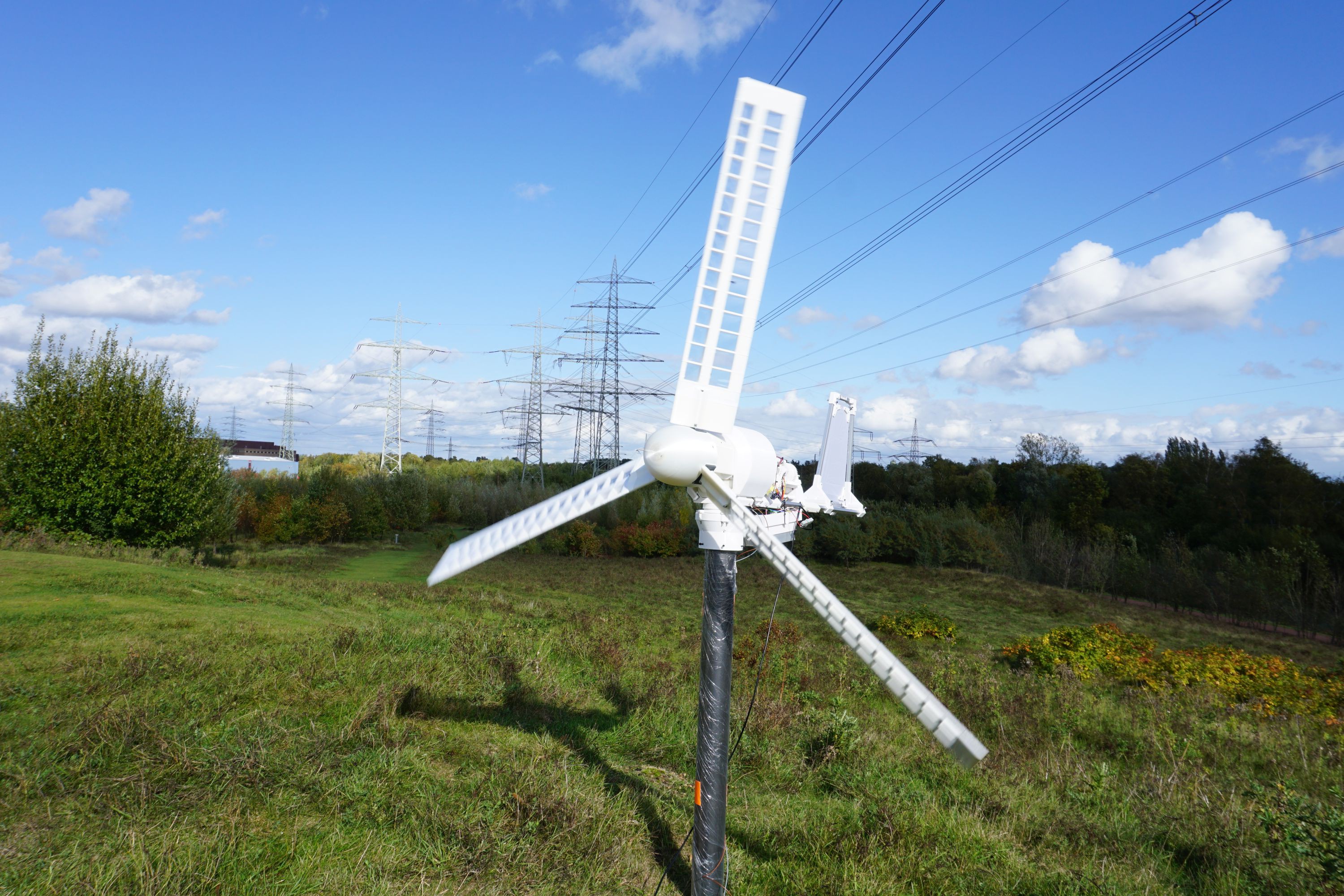
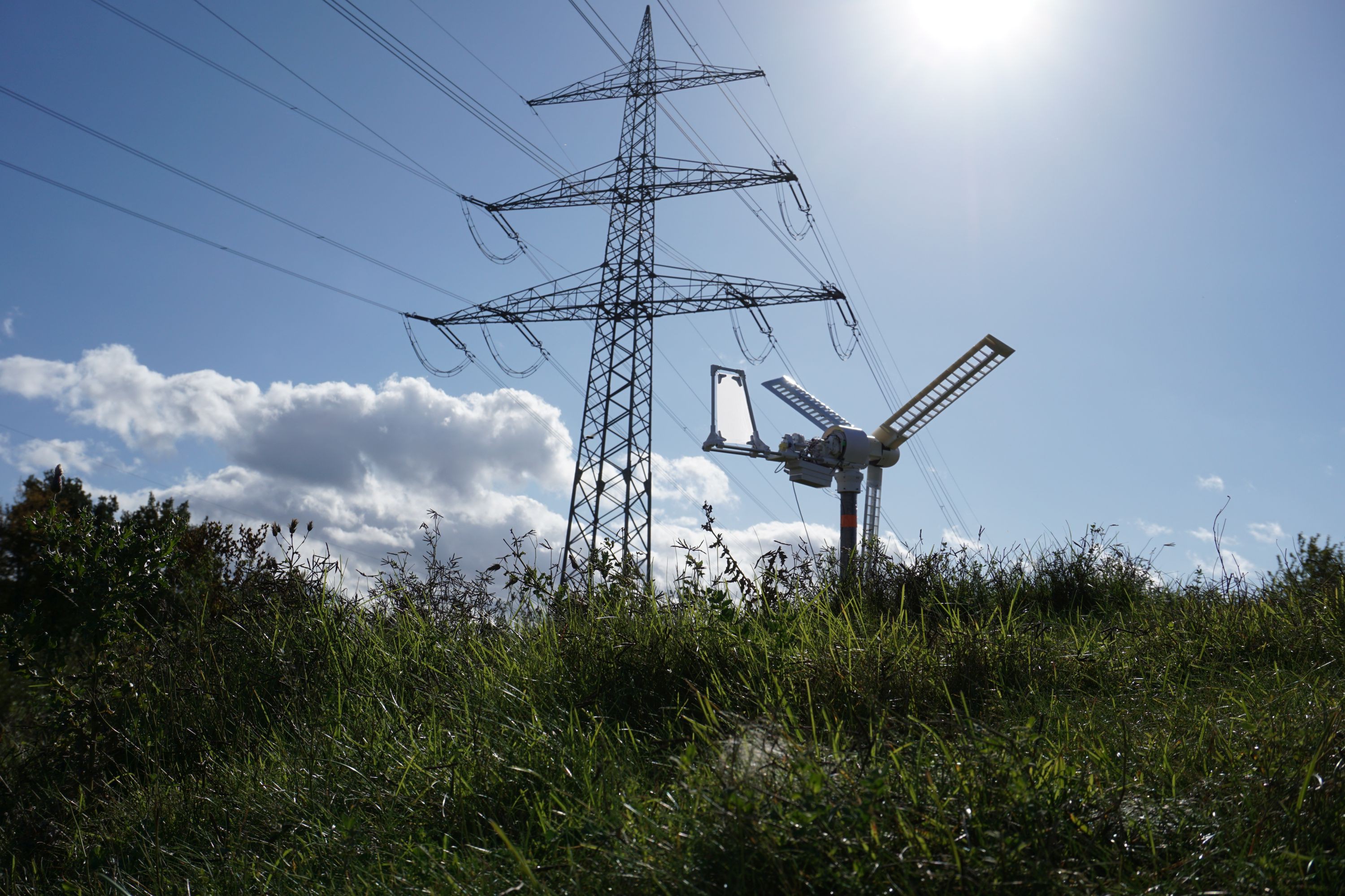
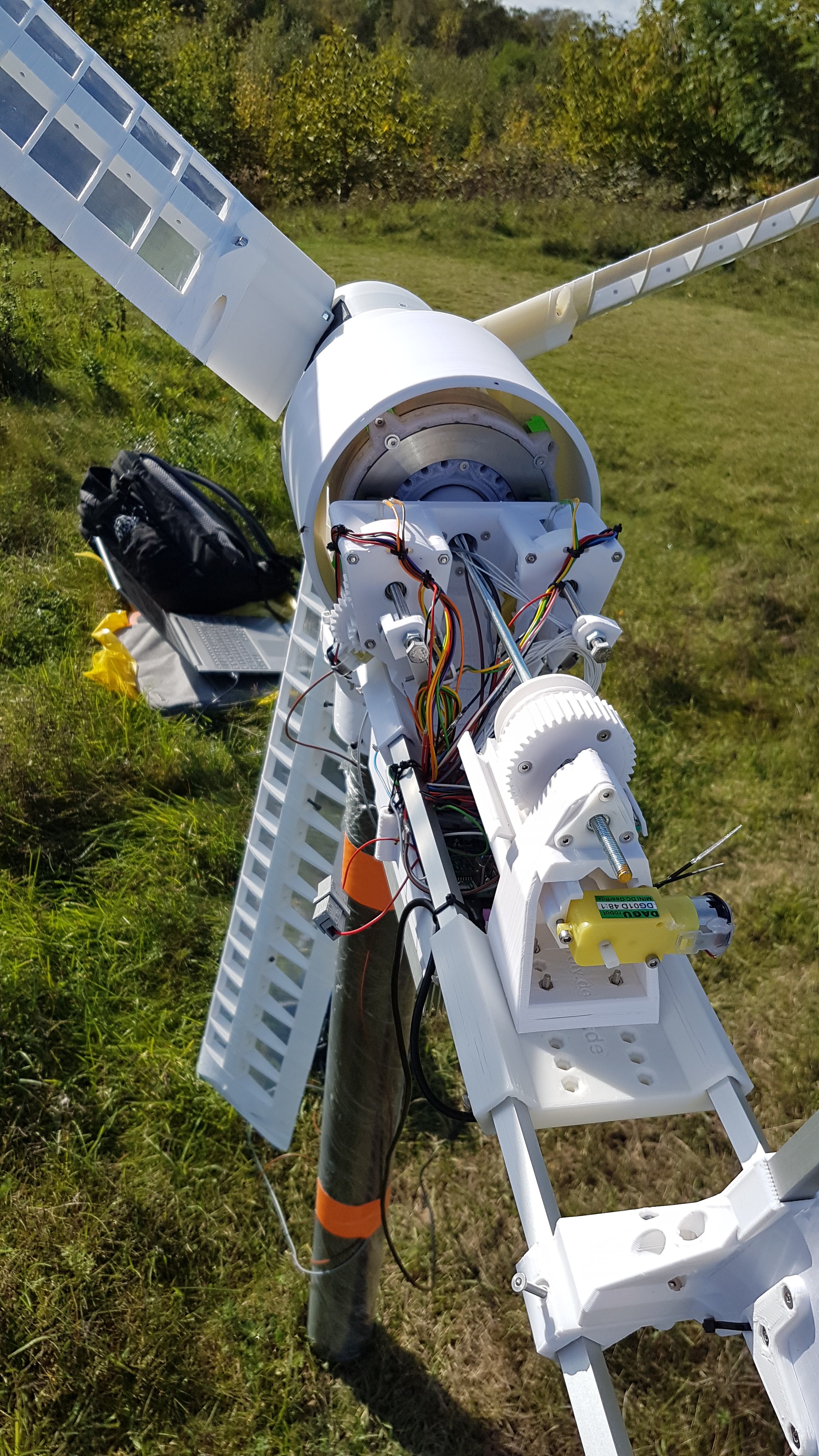
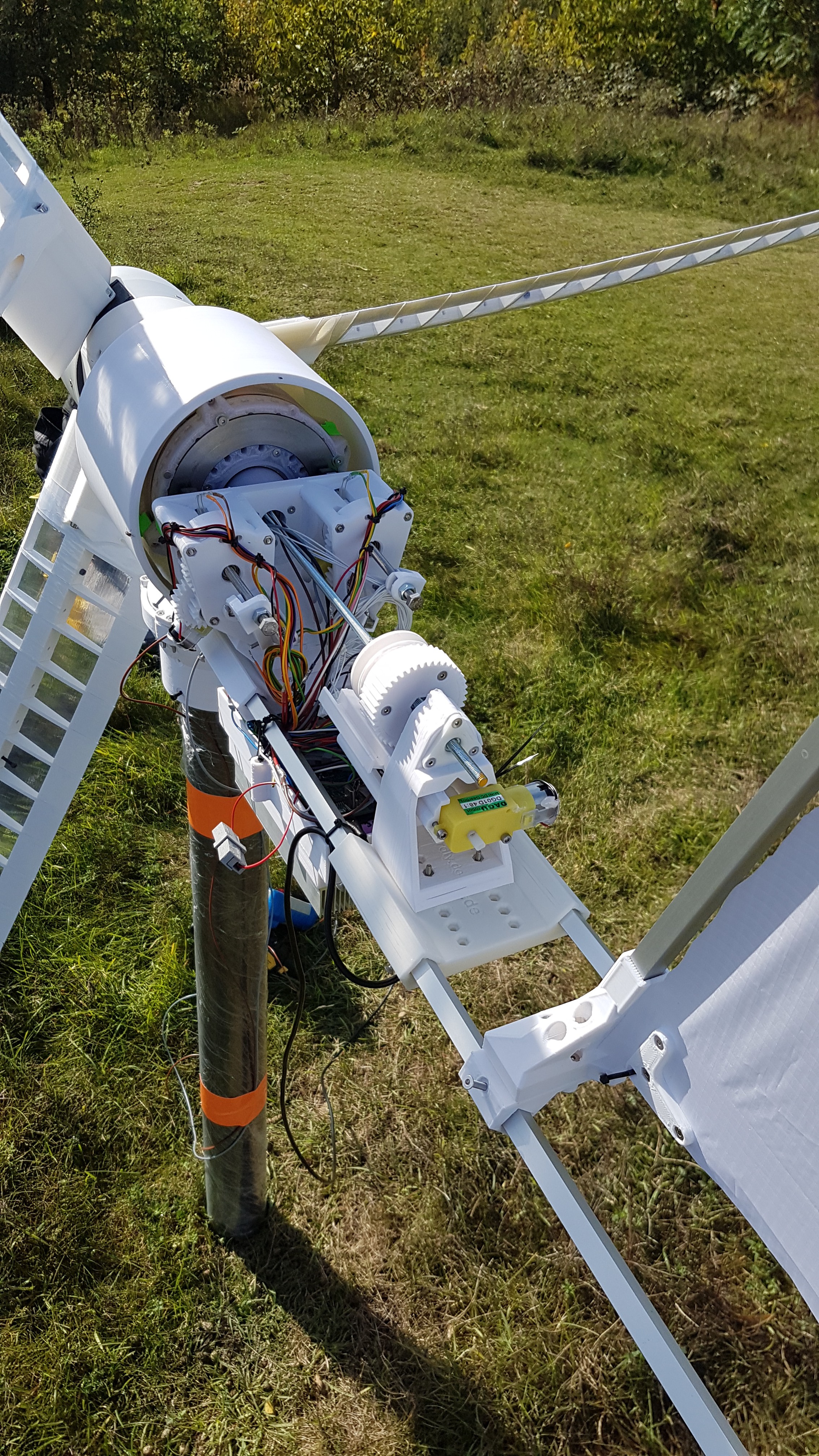
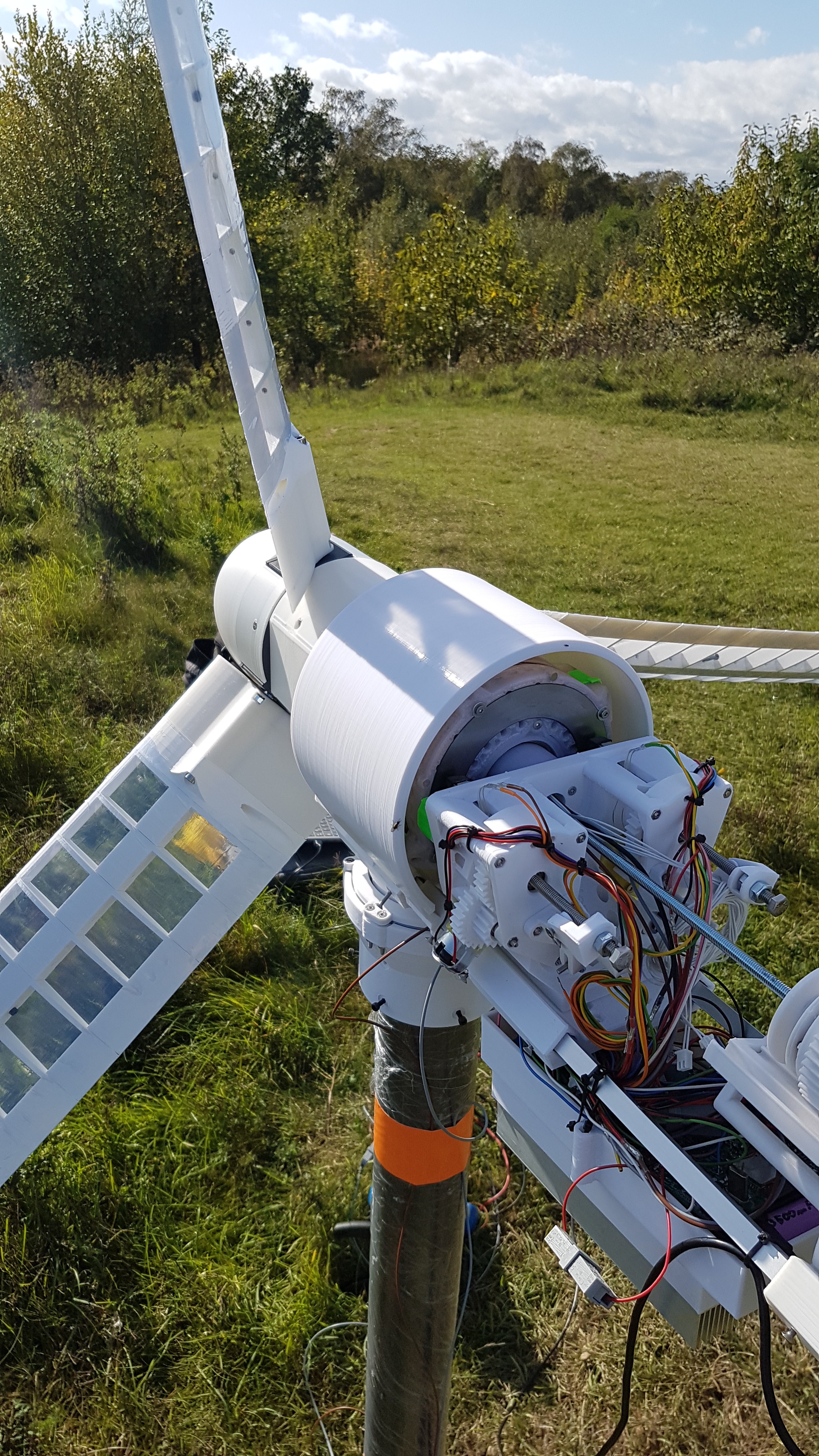
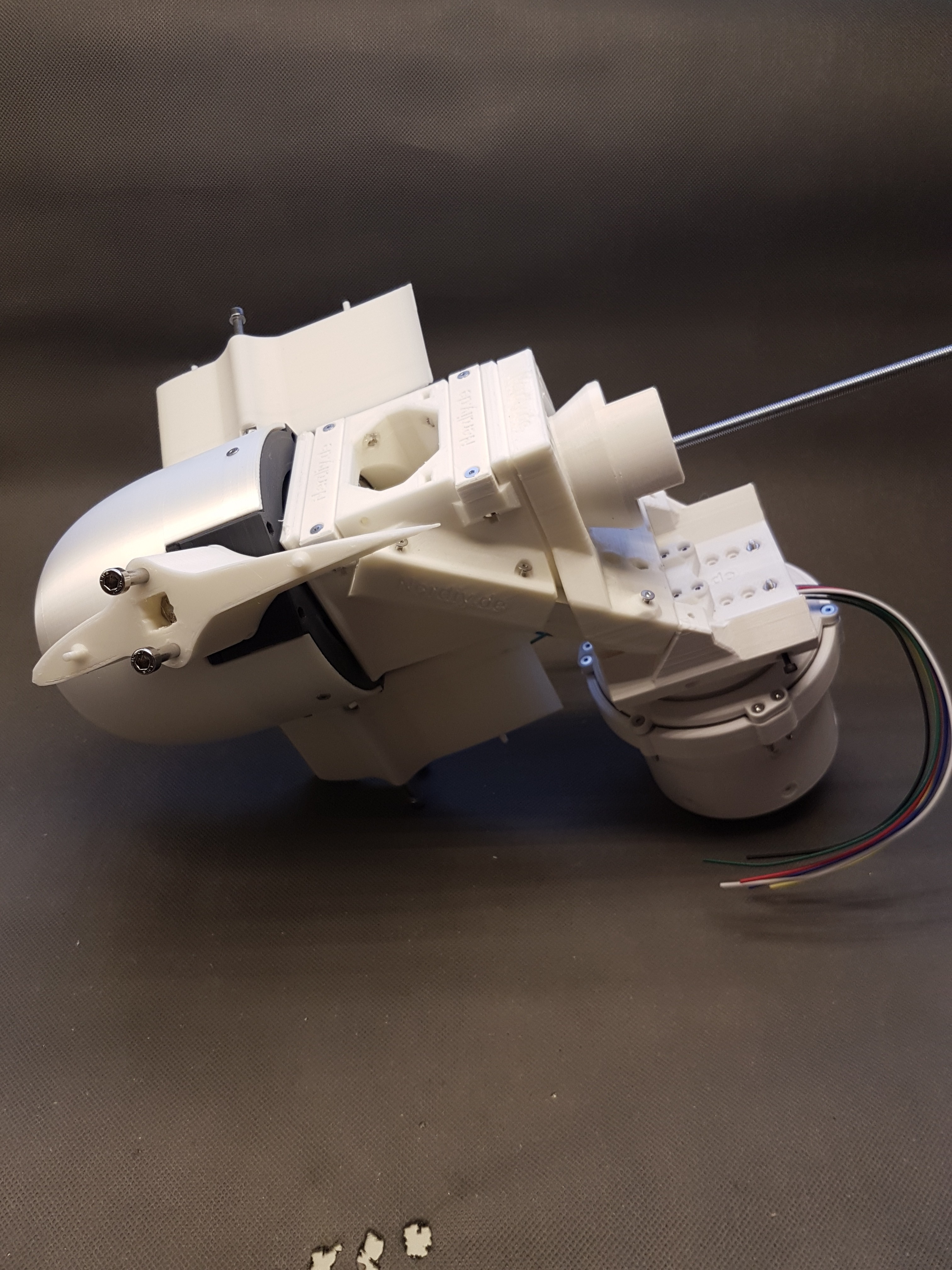
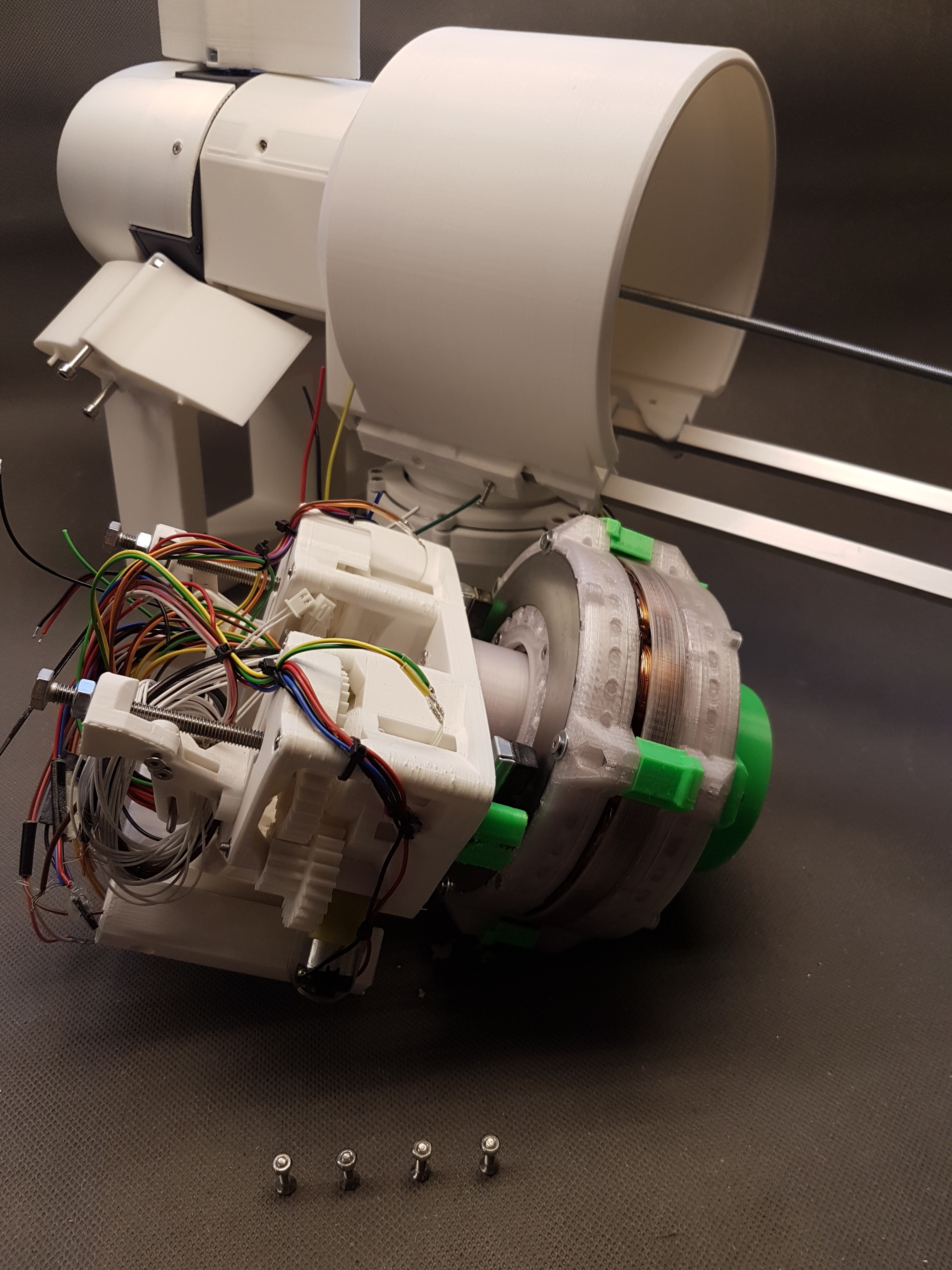
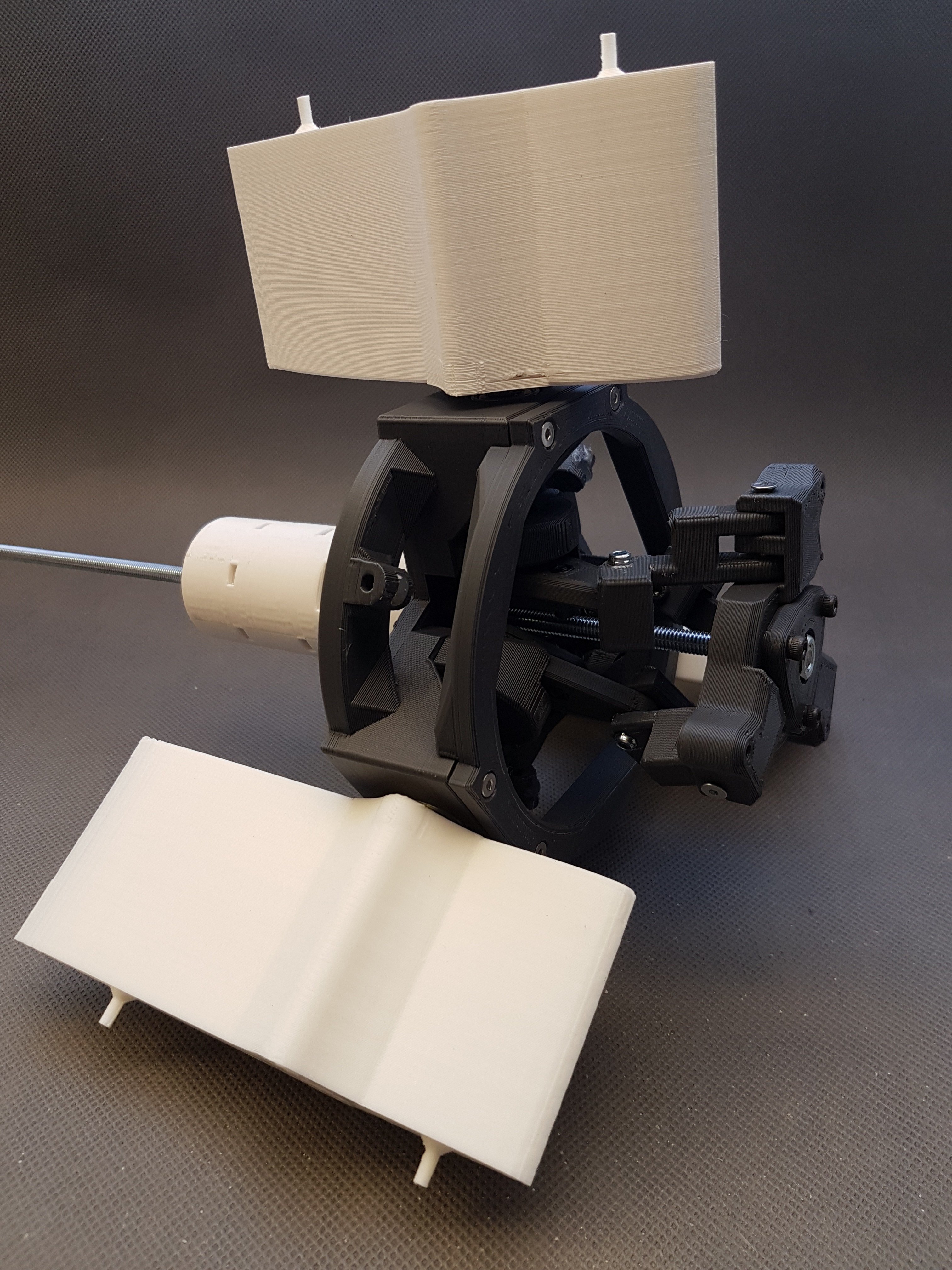
WinDIY on its first test run:
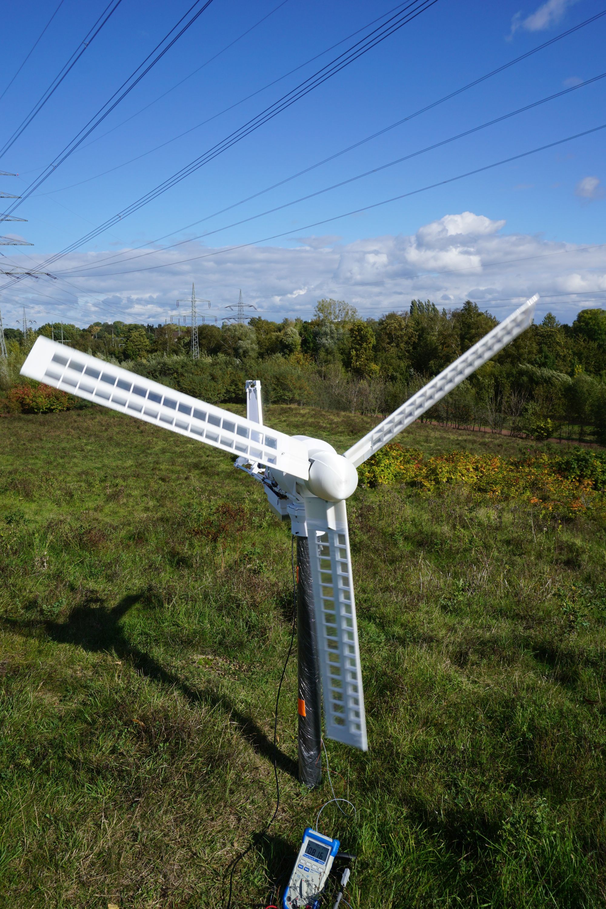
Side view:
(Wind vane will be added soon)
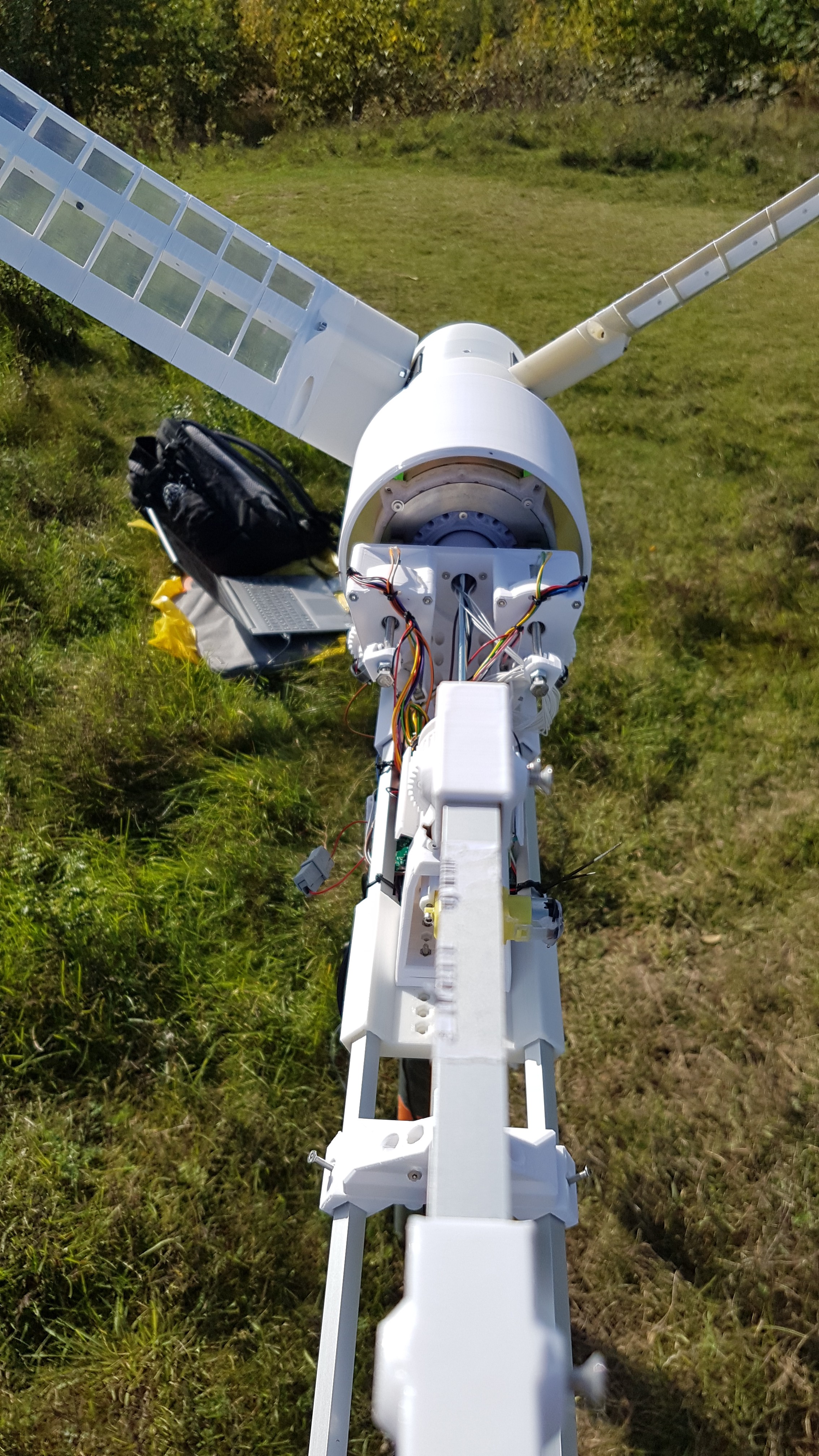
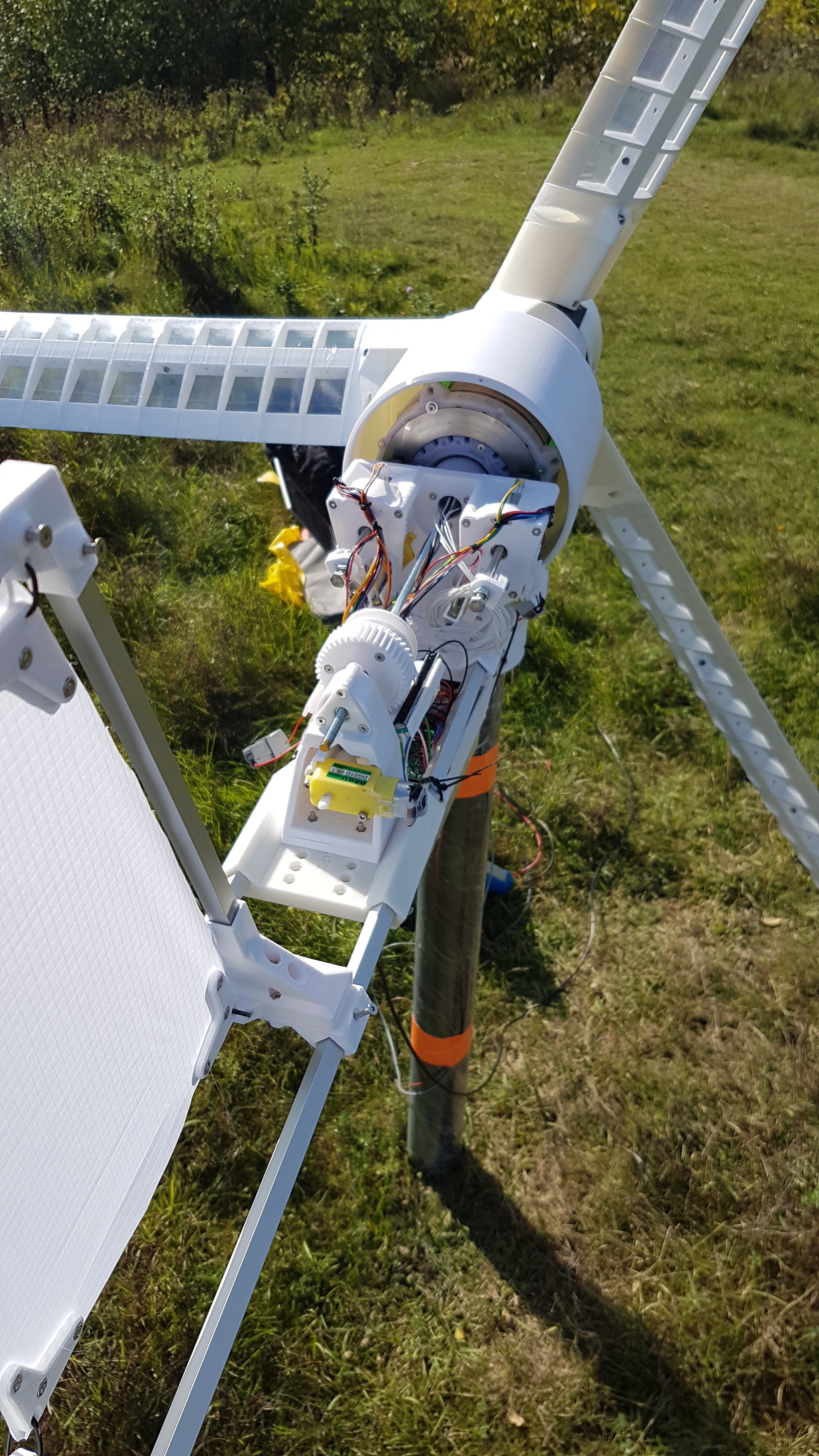
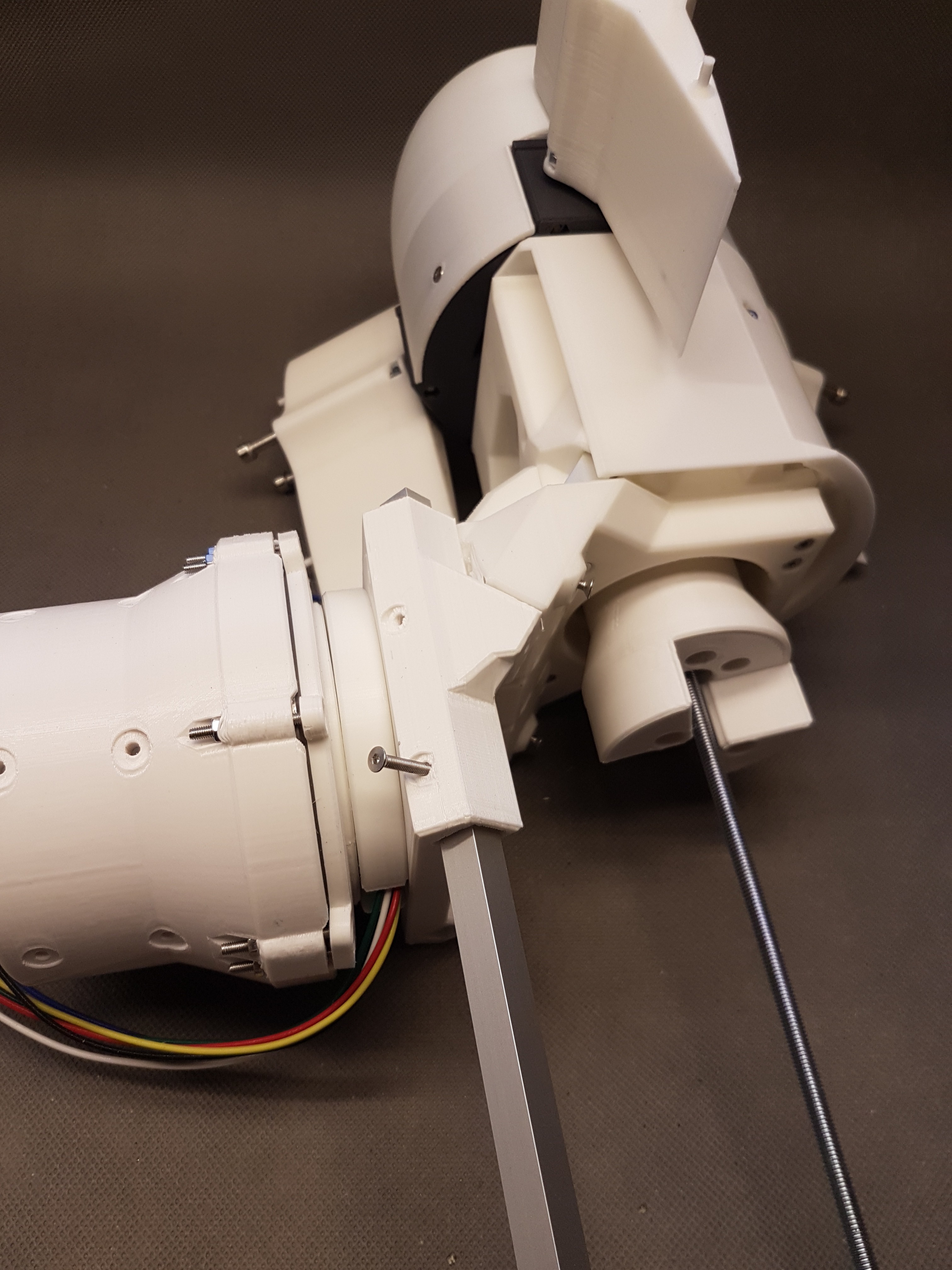
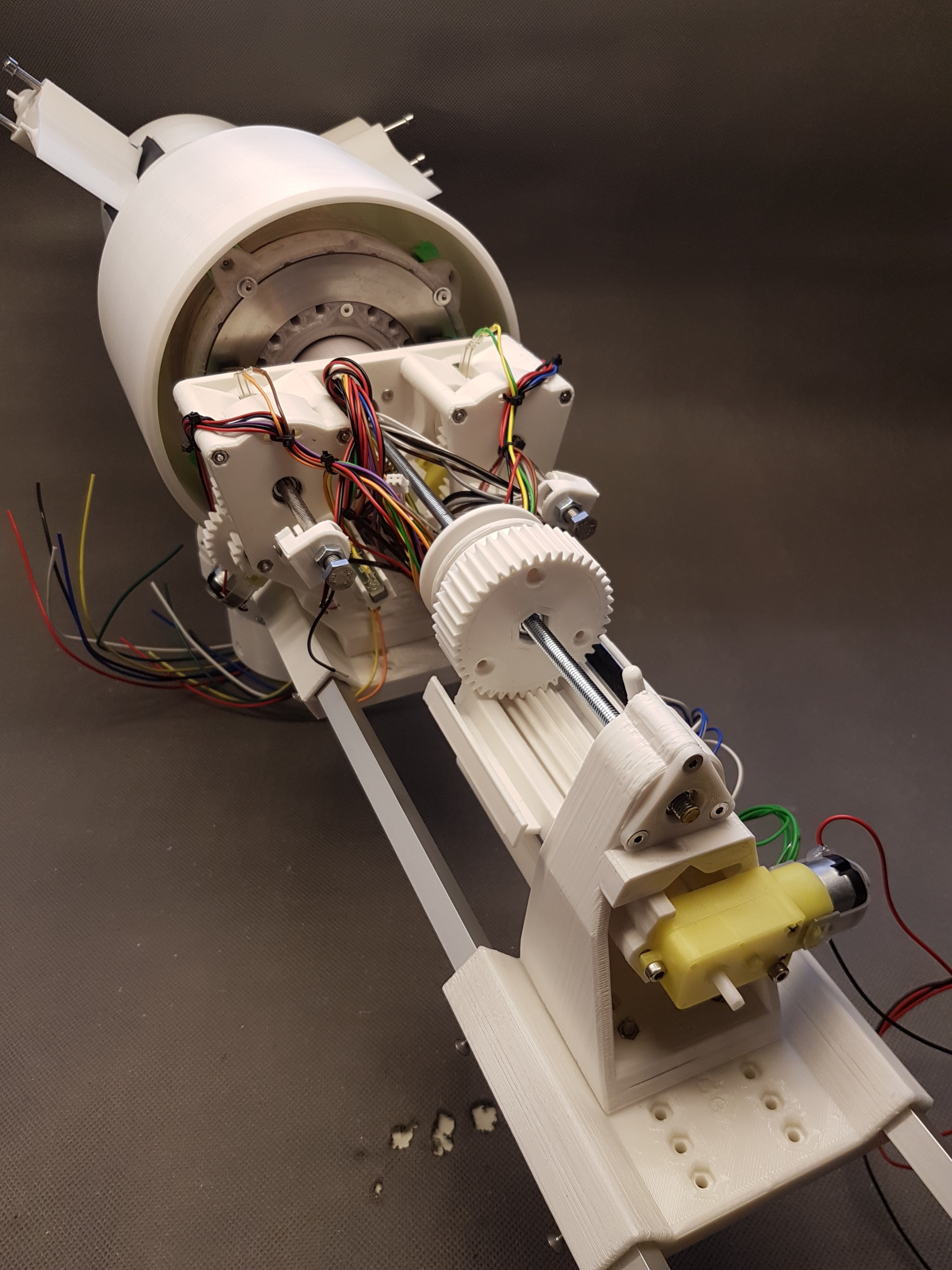
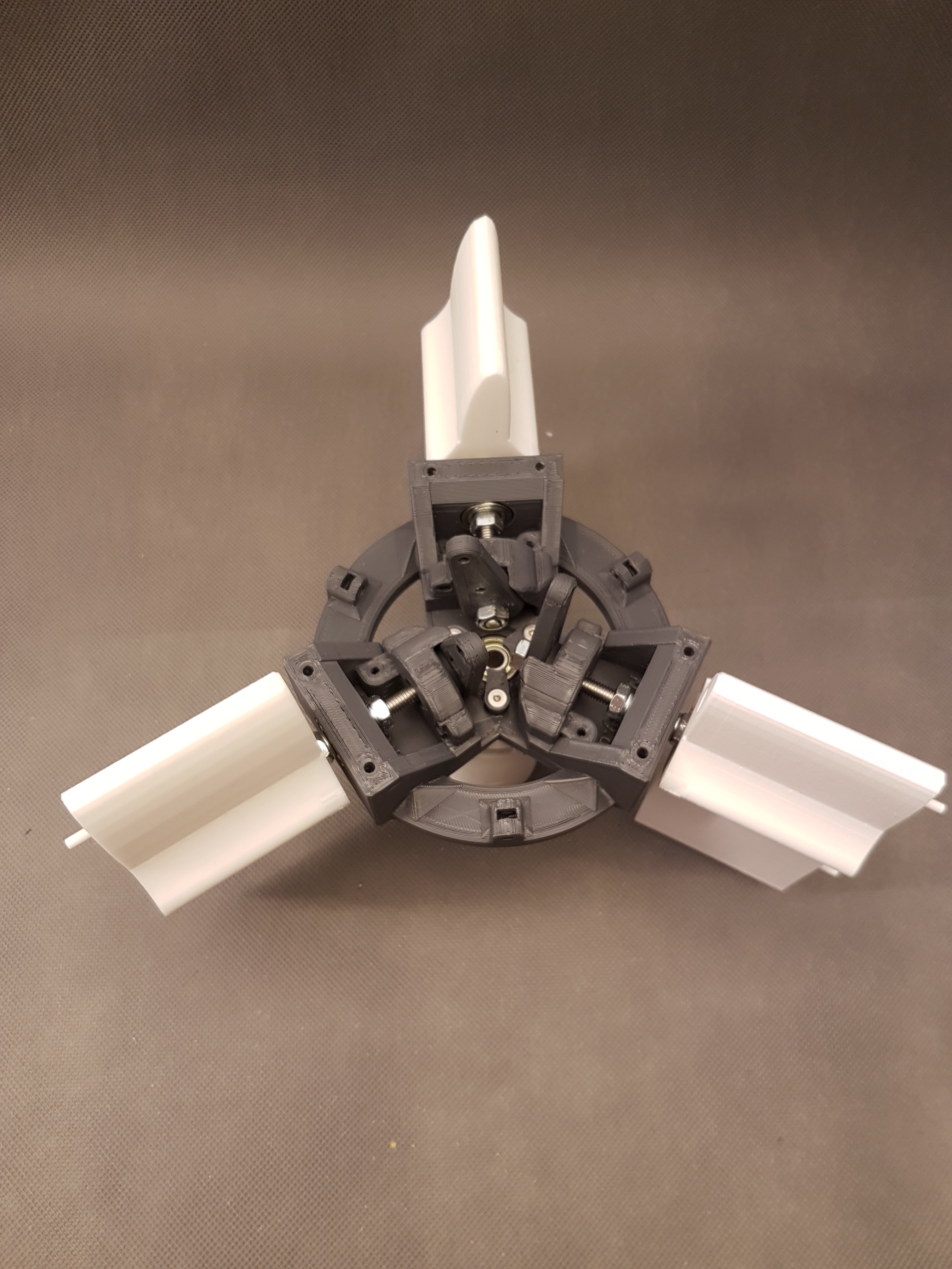
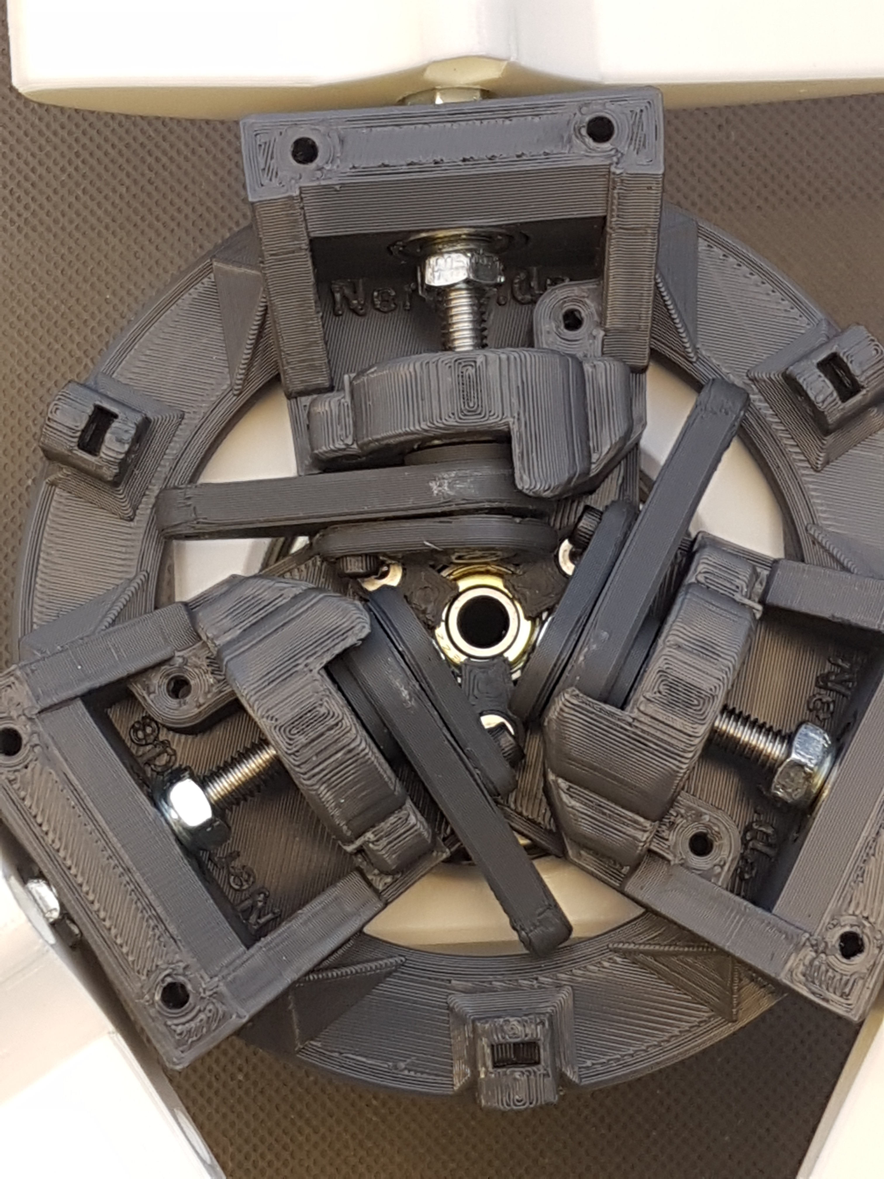
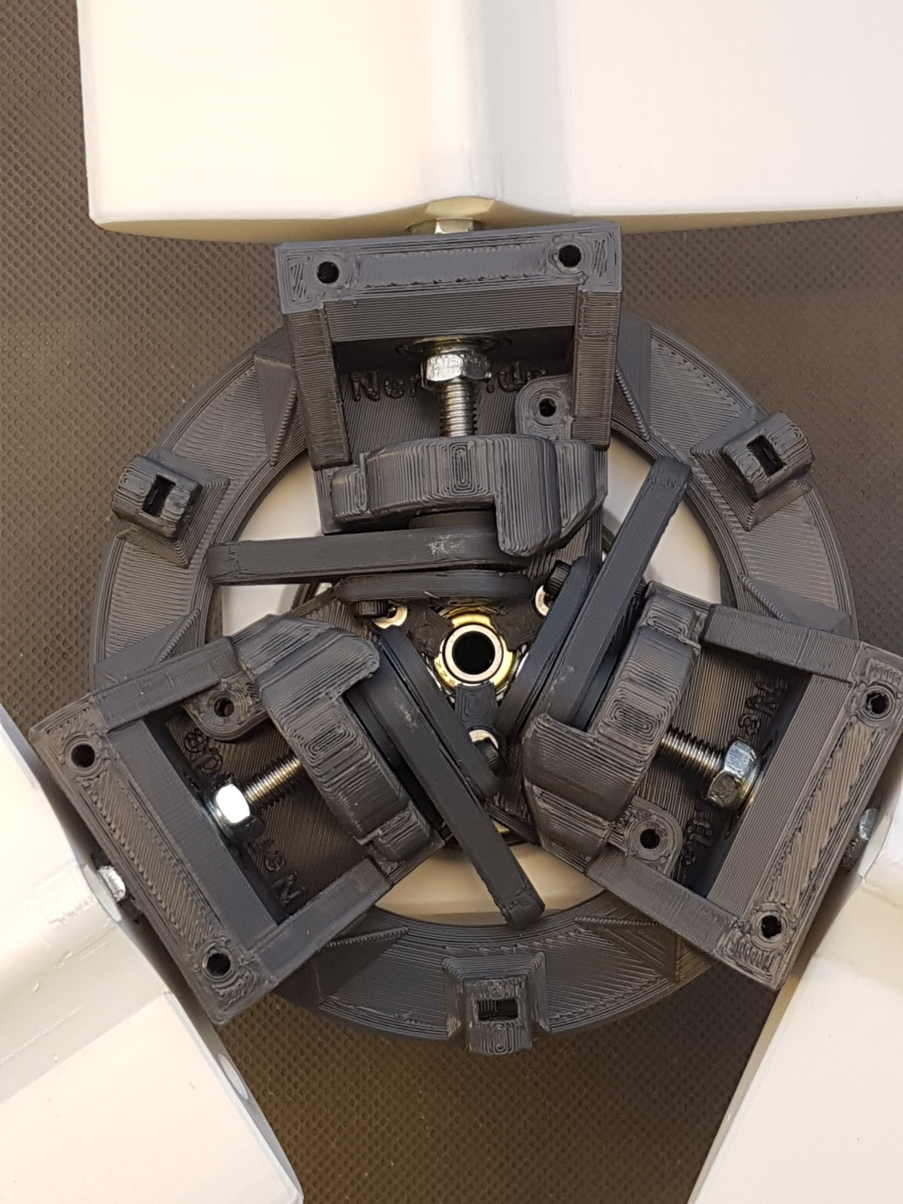
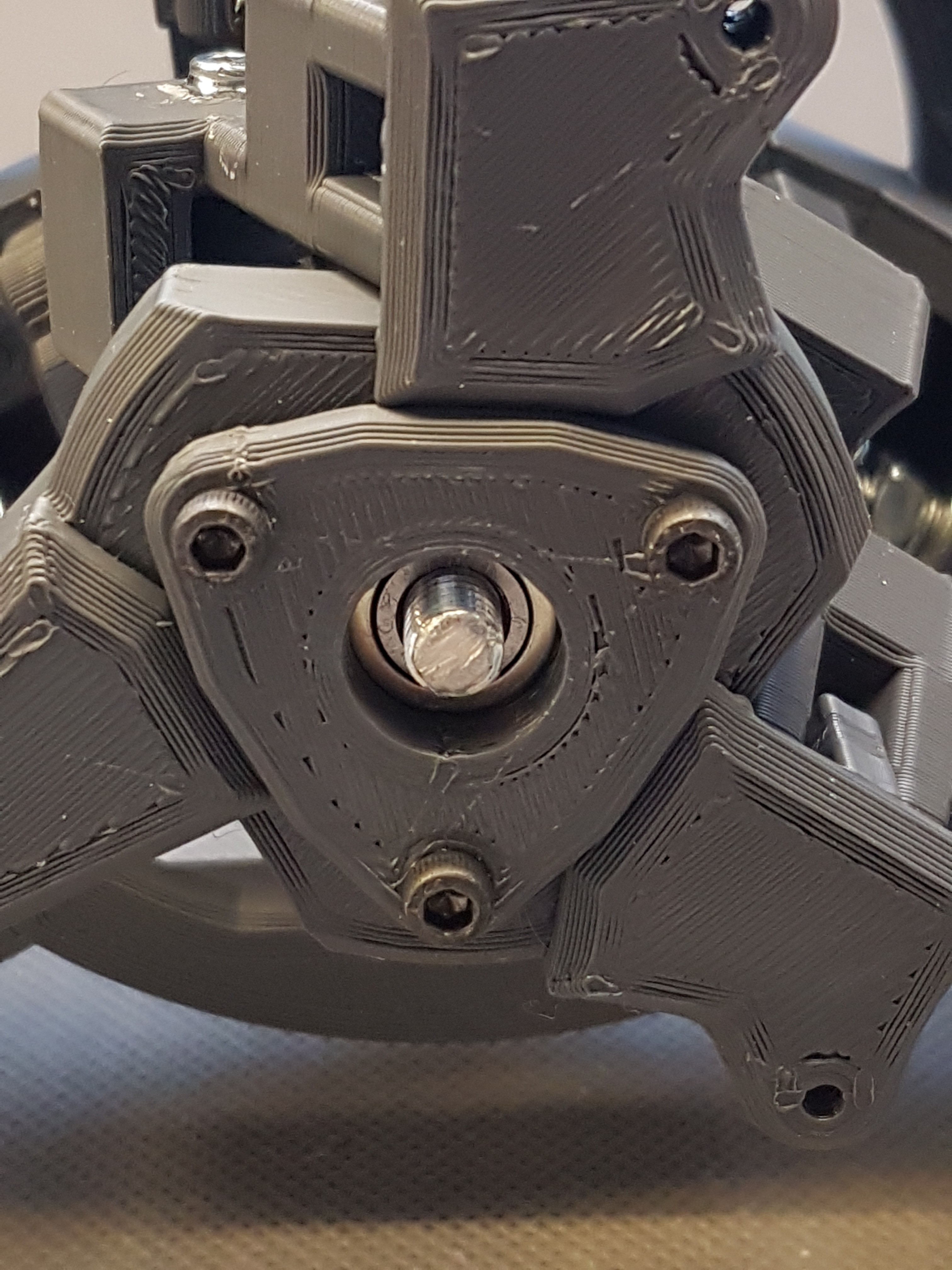
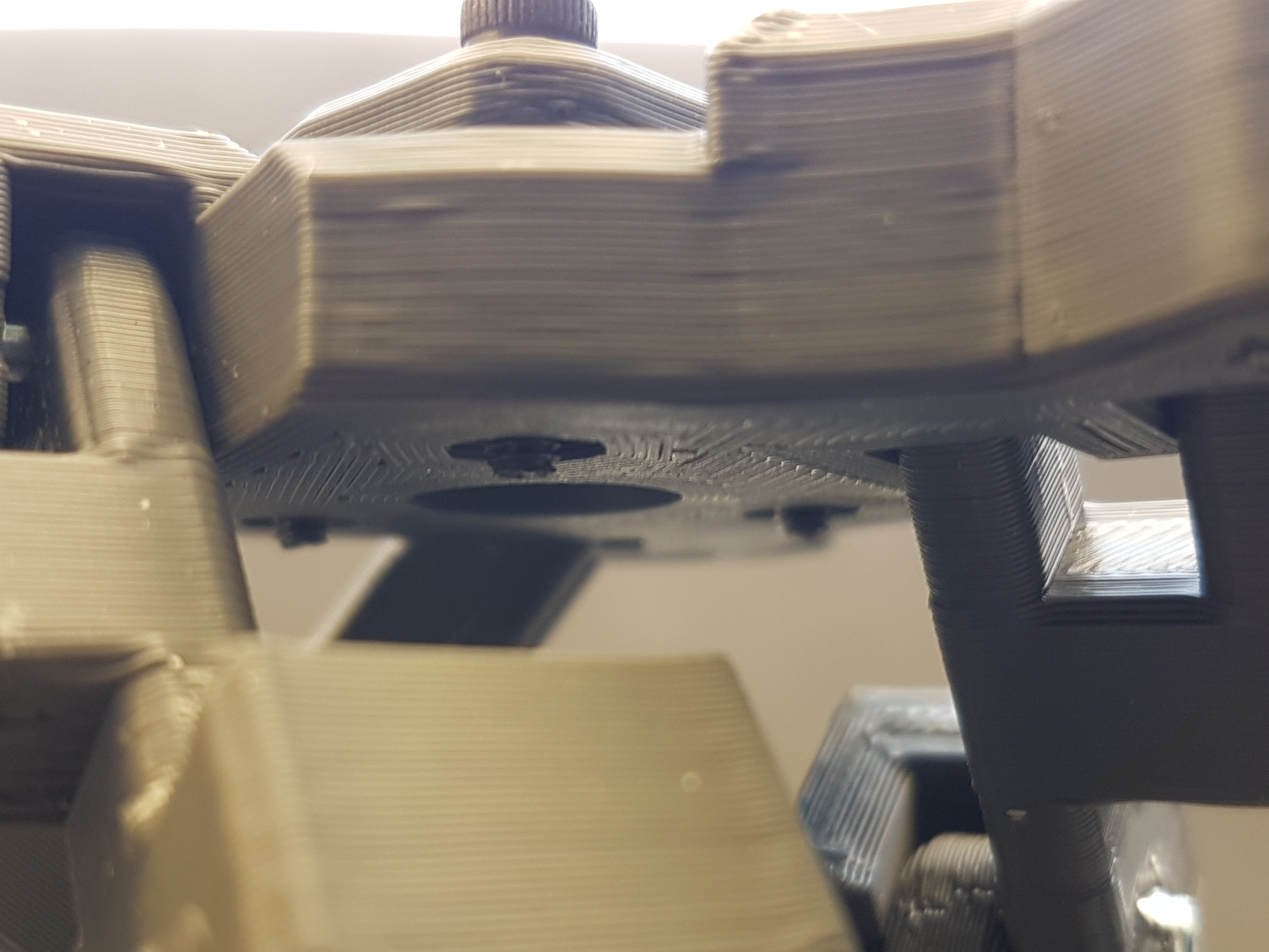
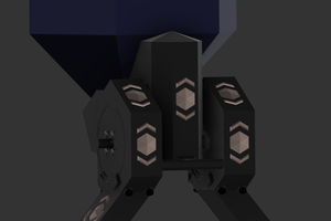
WinDIYs pitch actuator:
More infos: https://hackaday.io/project/172328/log/180247-the-pitch-actuator-in-action and here https://hackaday.io/project/172328/log/179105-windiys-hub-oh-my-god-mechanics
ToDo:
- Test the heat sink bracket for the load resistors: pending
- Design controller circuit: pending
- Create assembly instructions for hub: pending
- Create assembly instructions for wing: pending
- Create assembly instructions for the wind vane: pending
- Create assembly instructions for turret: pending
- Create assembly instructions for main axis: pending
- Design adapters for other standpipe diameters and also square bars (including clamping jaws): pending
Finished features:
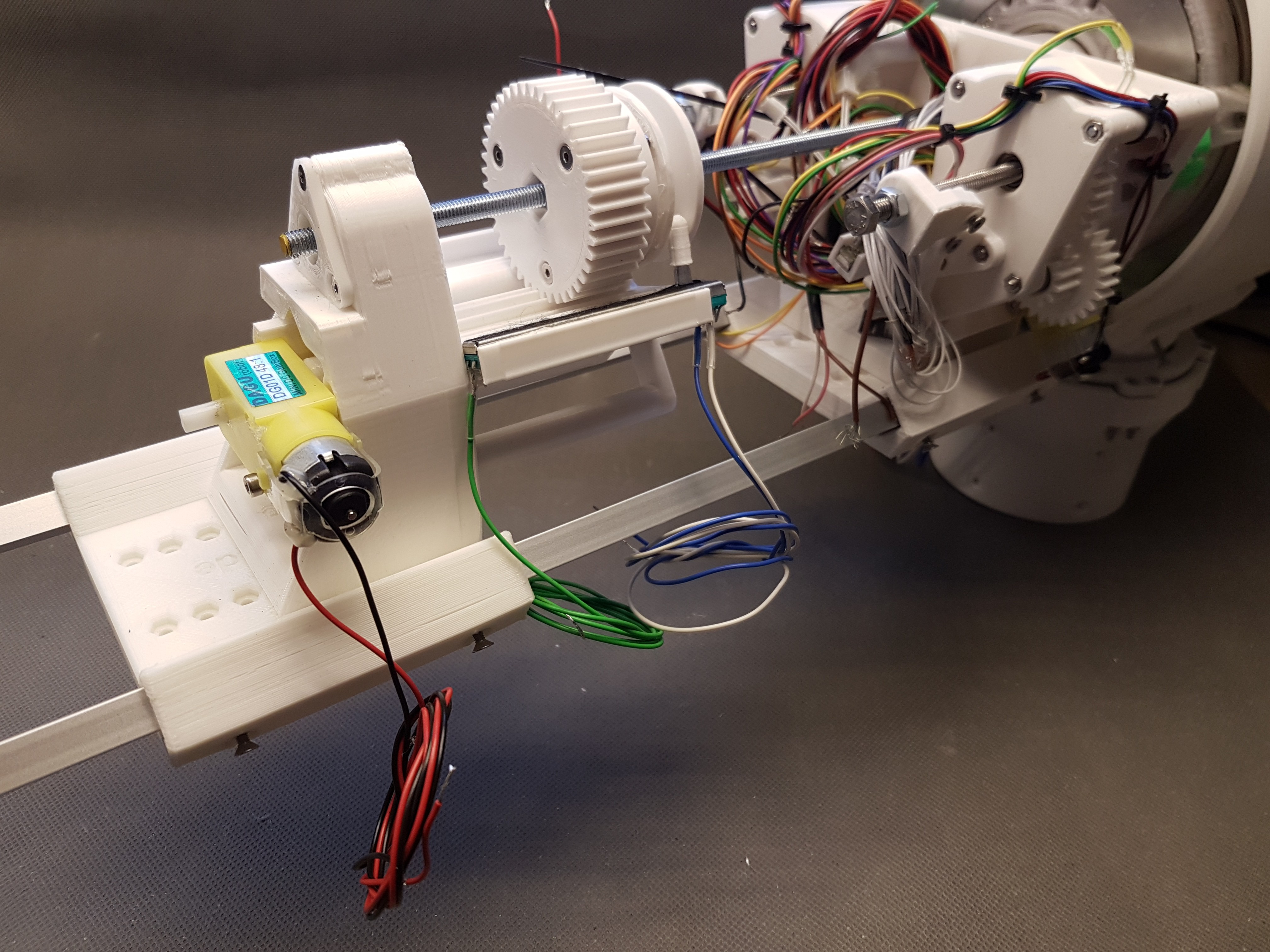
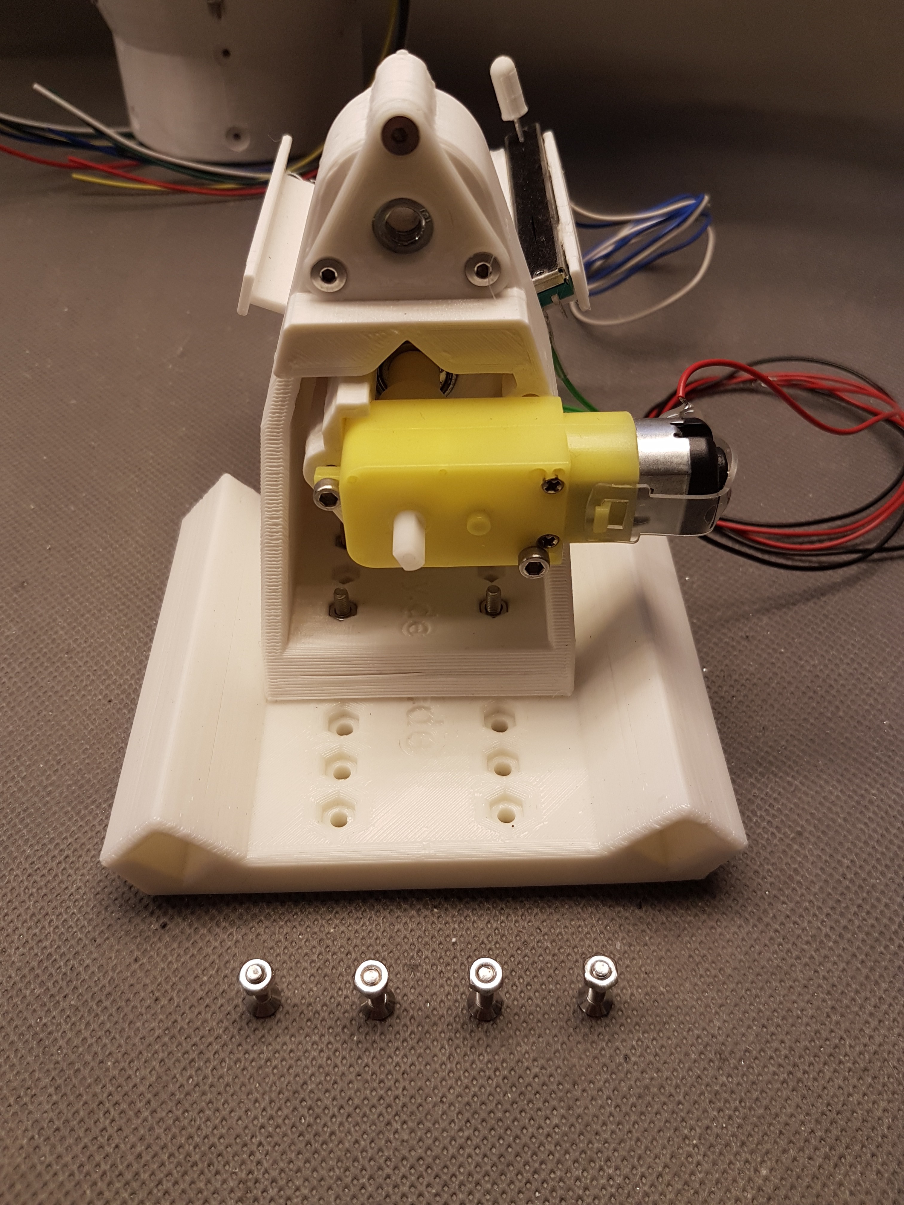
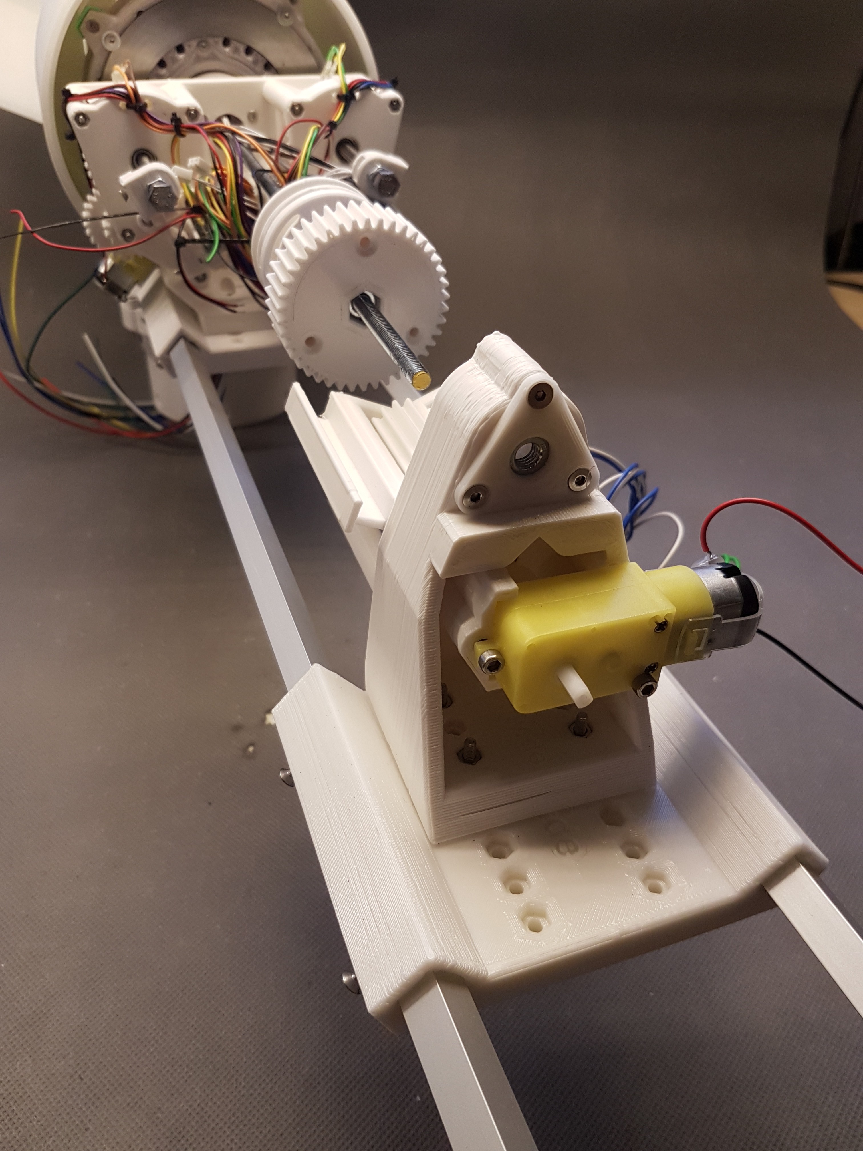
- Design adapter for driving the main axis via a DC motor: done: https://hackaday.io/project/172445/log/180101-test-stand-for-the-nerdiskerator
- Design and print mount for pitch-actuator: done: https://hackaday.io/project/172328/log/180247-the-pitch-actuator-in-action
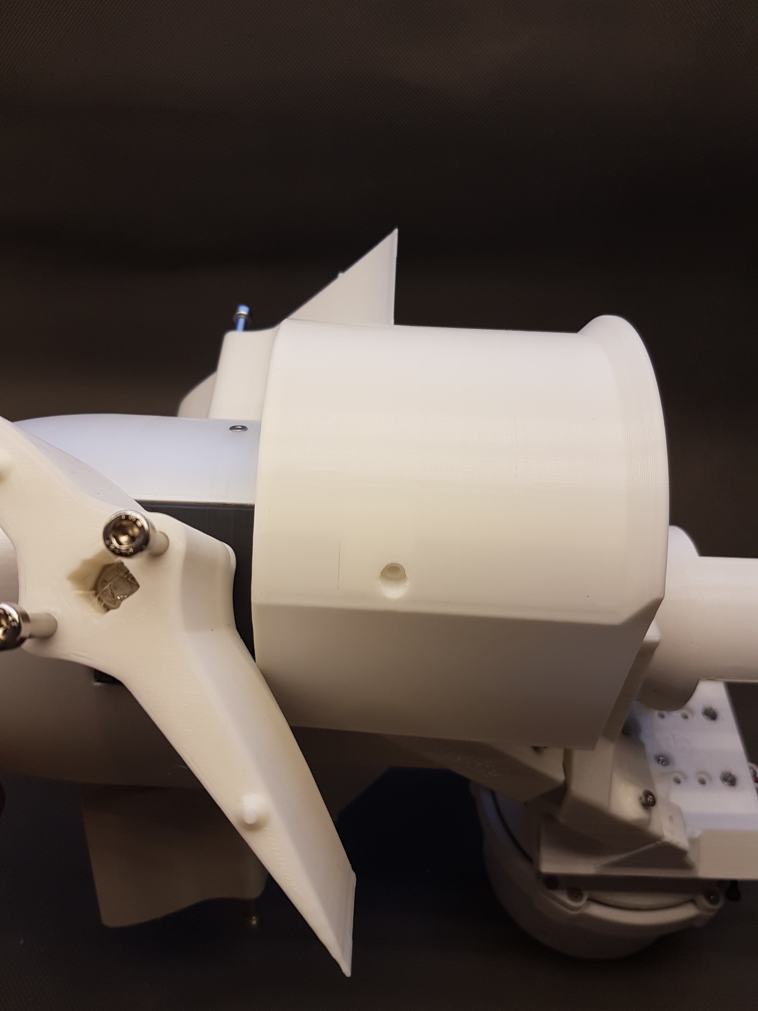
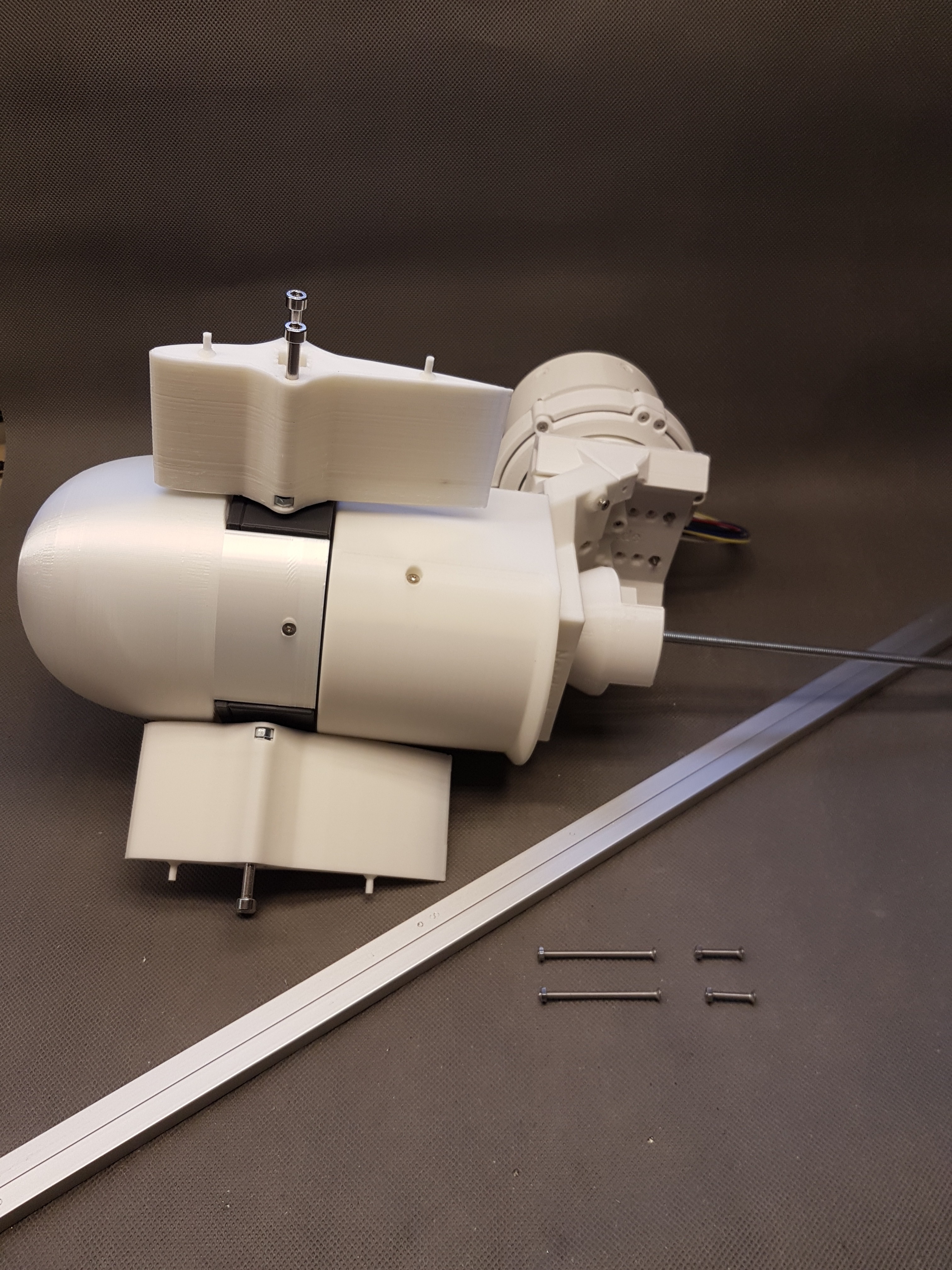
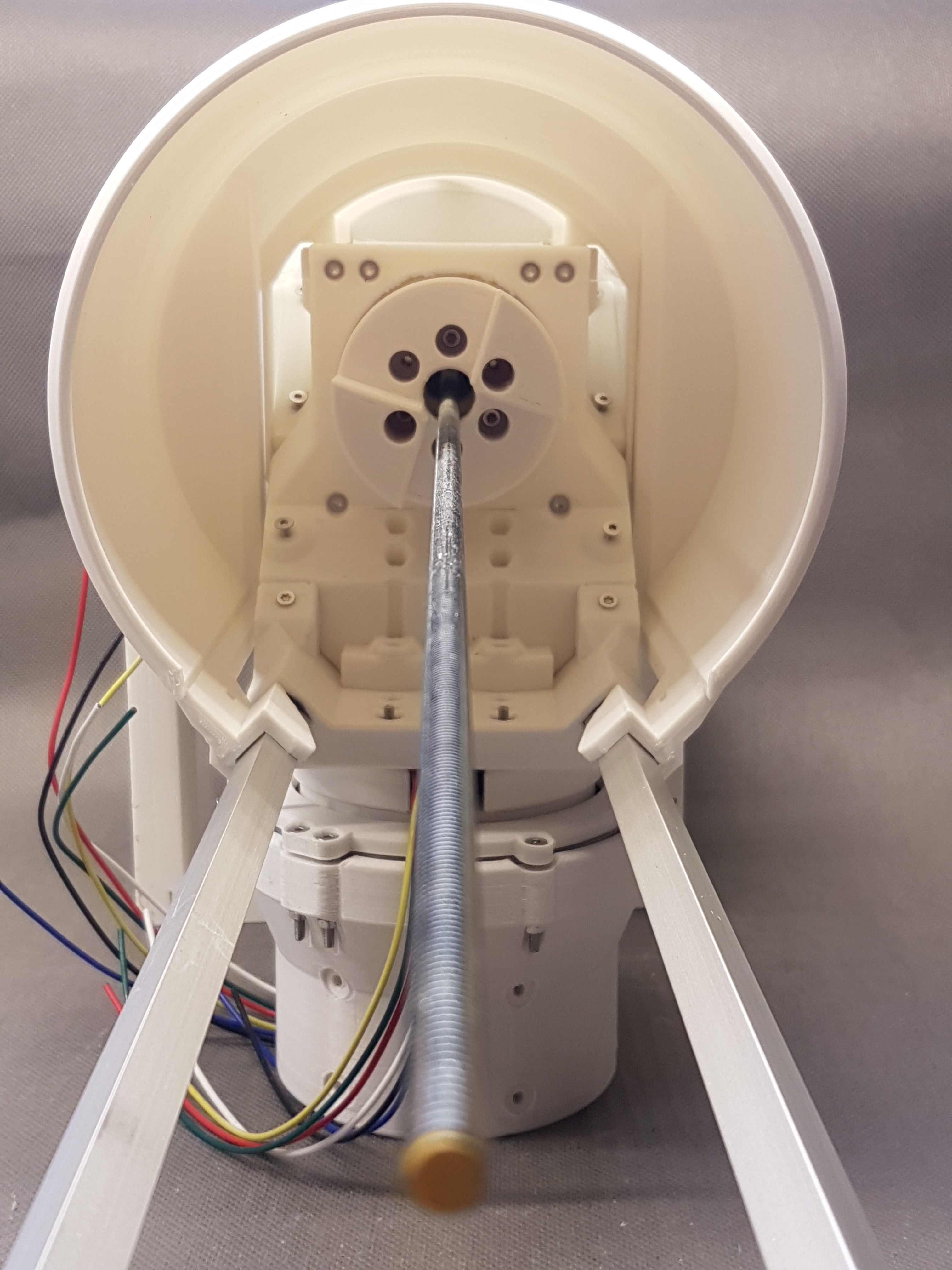
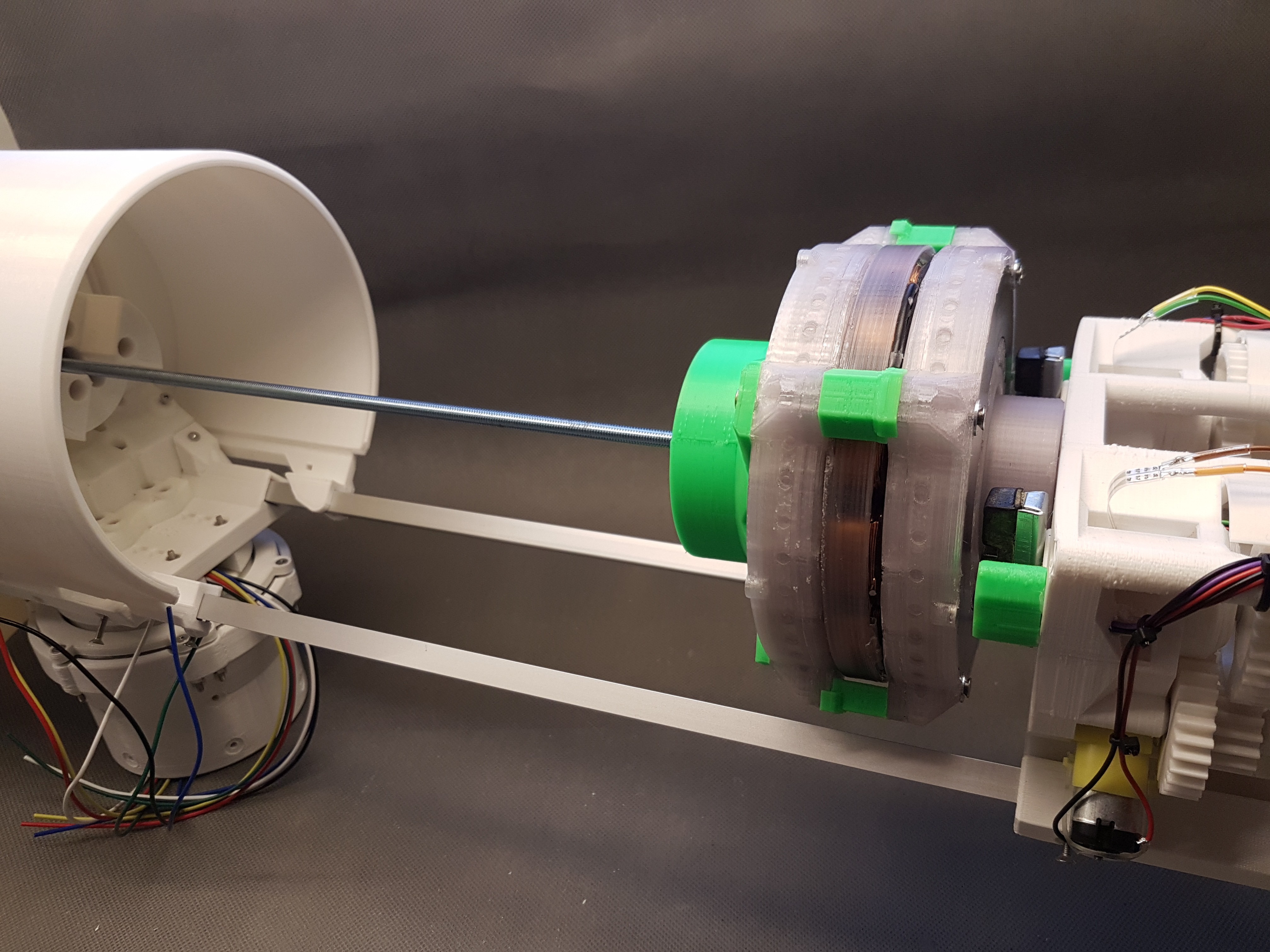
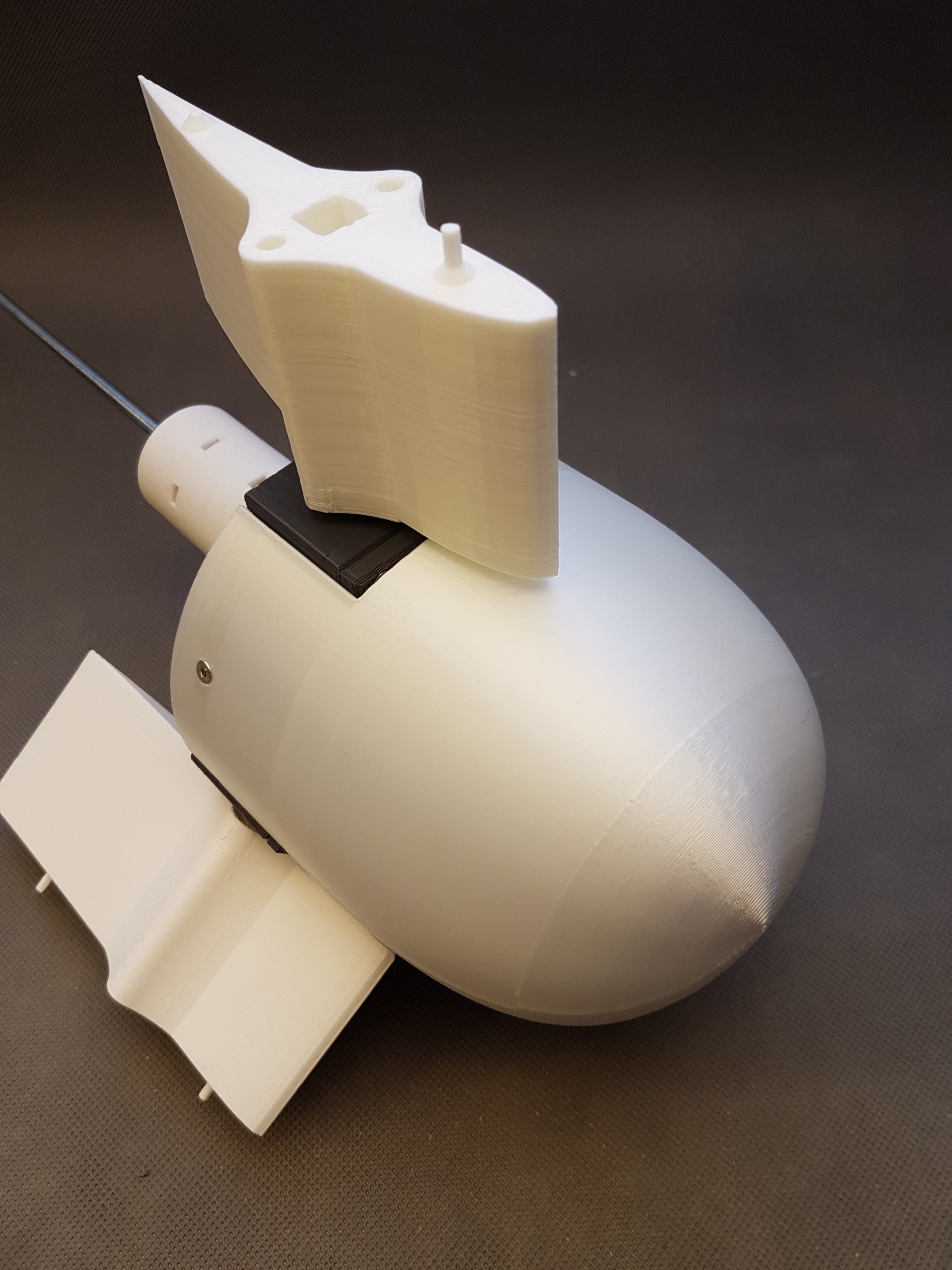
- Design and print the main axis housing: done:
- Mount the wind vane: designed and printed, not assembled yet
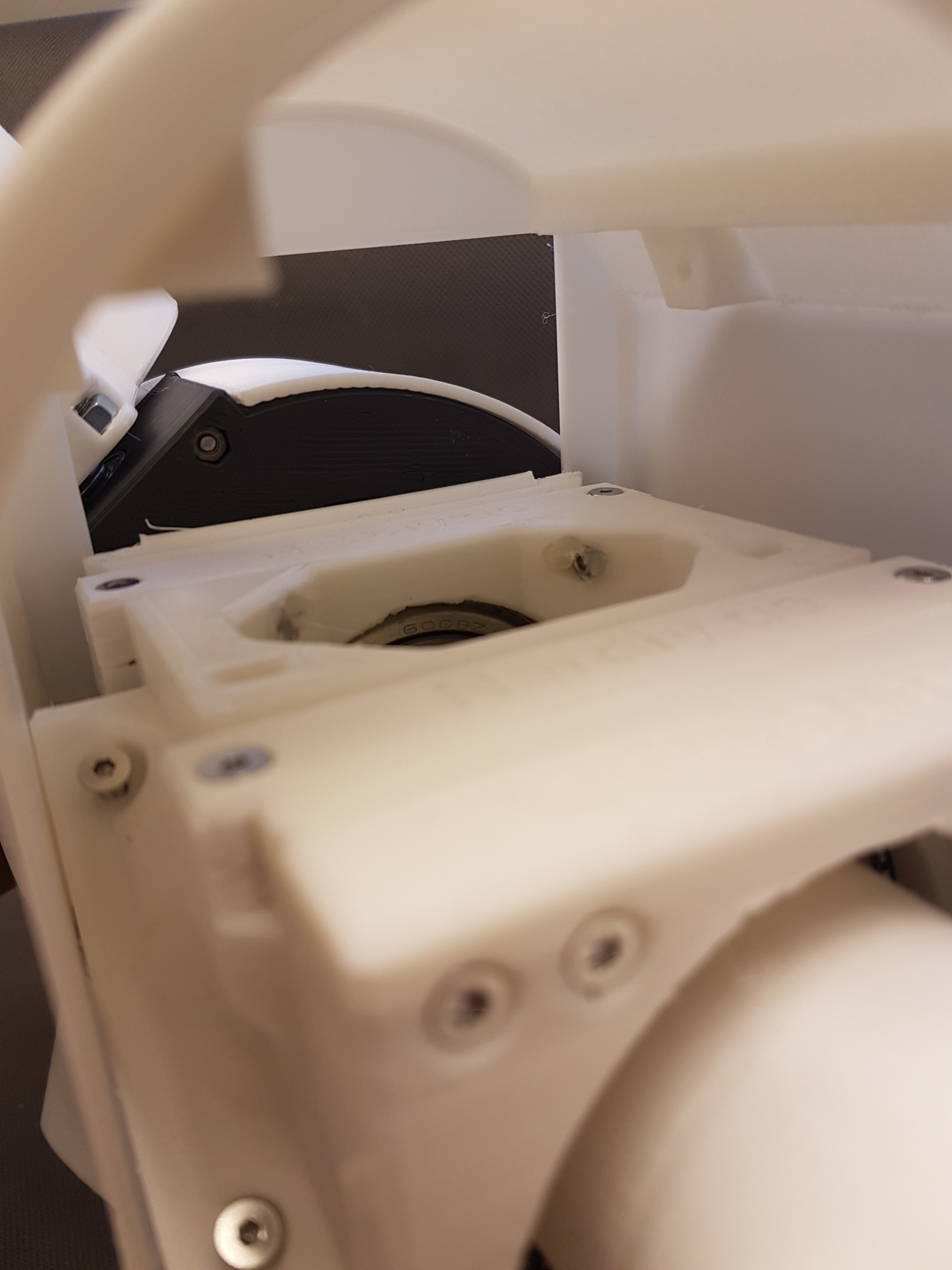
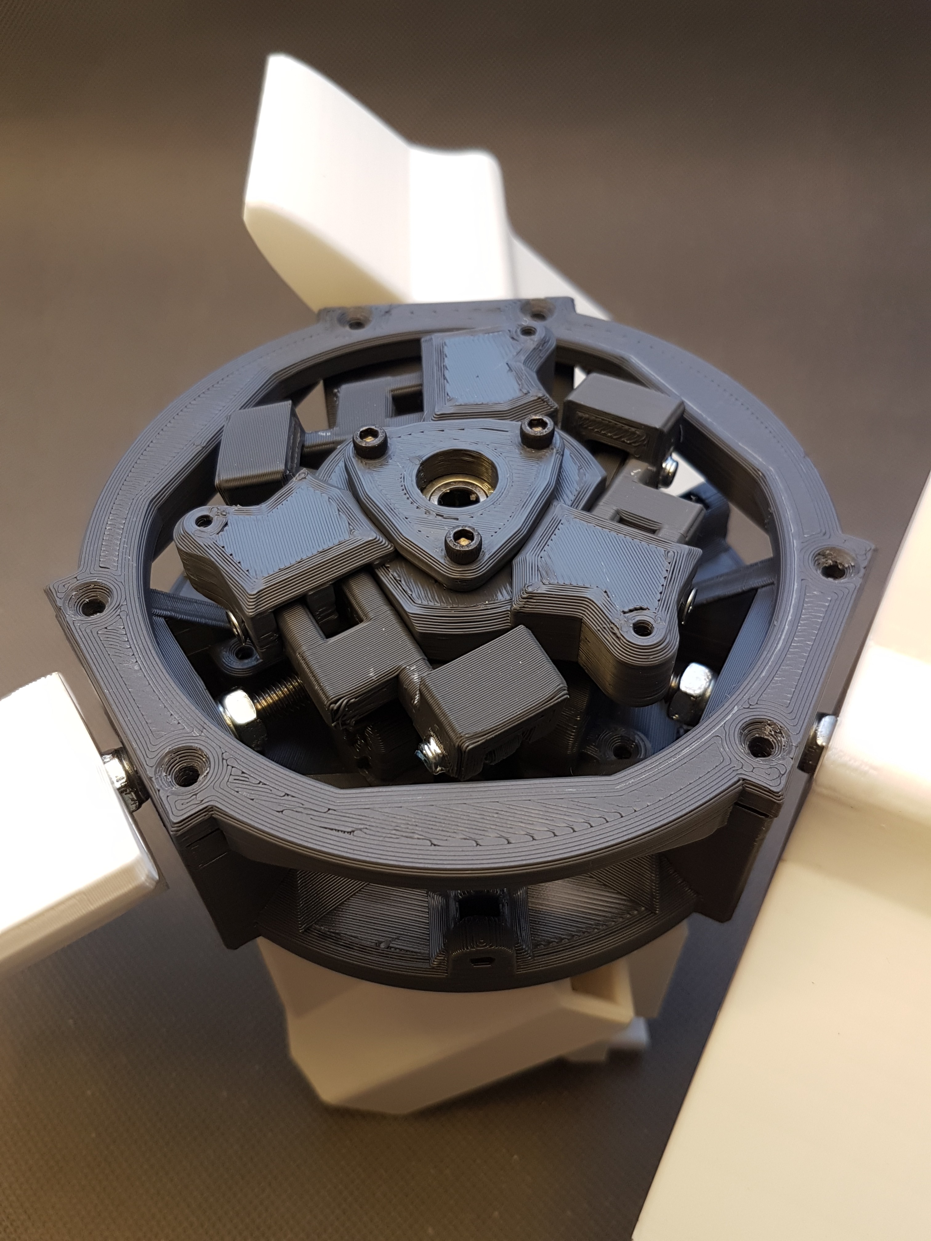
- Design Hub mechanics that allow plade-pitch adjustment: done: https://hackaday.io/project/172328/log/179105-windiys-hub-oh-my-god-mechanics
1. Why (in general):
I actually started this project as a follow-up project from the Nerdiskerator (infos here: https://hackaday.io/project/172445-nerdiskerator-a-3d-printed-disk-generator). This is a disk generator that I initially built as a kind of experiment. When I had successfully built it up I thought "Just putting it on the shelf is a shame". (I like to build things that have a practical use even after they have been set up.) So the Nerdiskerator should also get a practical use and maybe even relieve my electricity bill a bit. :)
Since I have no flowing water in the area, a water turbine is unfortunately not an option to drive the generator. Fortunately there is wind here where I live. Not much, but certainly enough to be able to harvest some free watts from Mother Earth here and there.
When researching for available and easy replicable wind turbine designs, I noticed that there is a lot of scattered information about building a wind generator yourself. Unfortunately, many of them were old and none of them seemed to me to be easy to replicate. I was hoping somehow that someone out there had already developed a design for a wind turbine that could easily be "reprinted" with a 3D printer.
I found a couple of designs, but either they weren't suitable or consisted of parts that could only be printed with very large 3D printers. Unfortunately, there was not a 3D printable design for a HAWT wind turbine as I imagined. I was looking for something easy scalable, easy adaptable and of course it should be safe.
Since I couldn't find something like this I decided to develop an own design of an easy replicable HAWT wind turbine. :)
2. Why a HAWT-Design:
First, because of the many technical arguments:
HAWT wind turbines are more efficient because all blades...
Read more »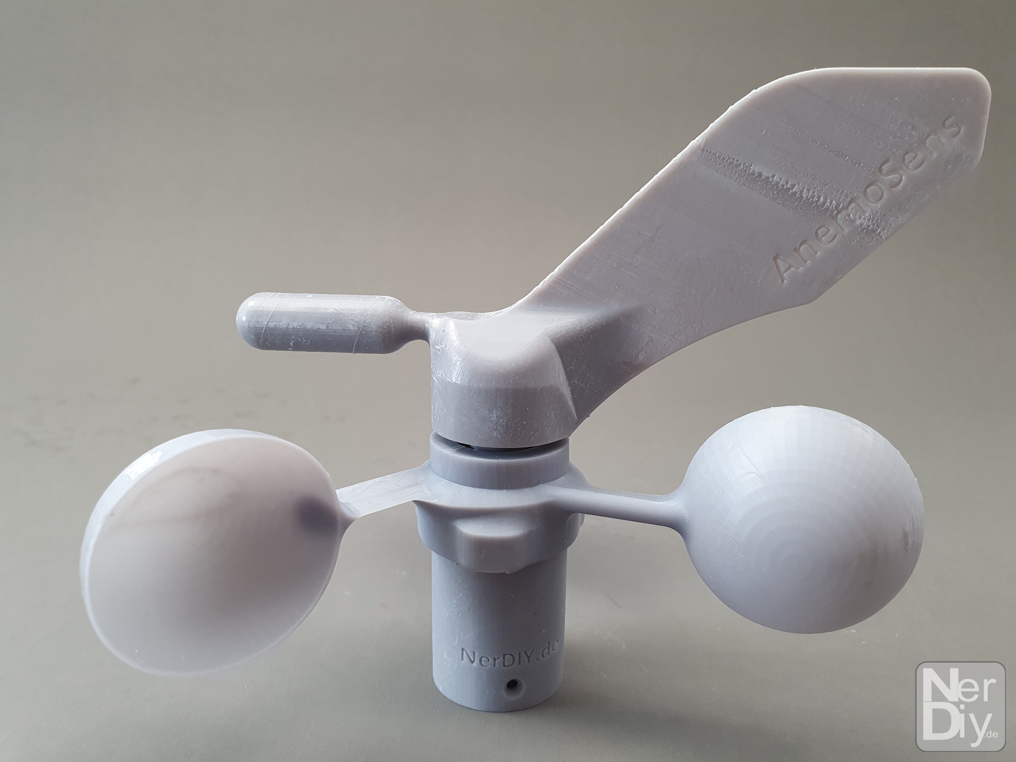


 Joseph Marlin
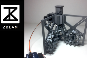
 Ronald Jaramillo
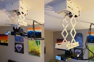
 Sam Baker
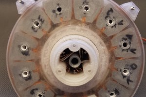
Is the alternator's power matched to that of the propeller? If so, how? Did you do your own calculations or is it based on an existing design?
For now, the generator seems way to small and will need a way to high RPM to achieve reasonable output. On your Instagram page I see that it delivers 2,5A*23V= 57.5W at 1200RPM. Your windturbine will do mostly 200-300rpm, so consequently the output won't be more than 14,4W at 5.75V whereas similar windturbines of that size will be producing 75W-100W. Because the propeller is barely loaded it will reach a dangerously high RPM leading the windturbine to self-destruct. Luckily you have brakes installed.
Props for all the effort you put into it though, it would be a good object to show kids or students how things like that work! :)