 Saimon
There are many similar projects, but in most of the cases, the LEDs are the WS2812 or similar LED.
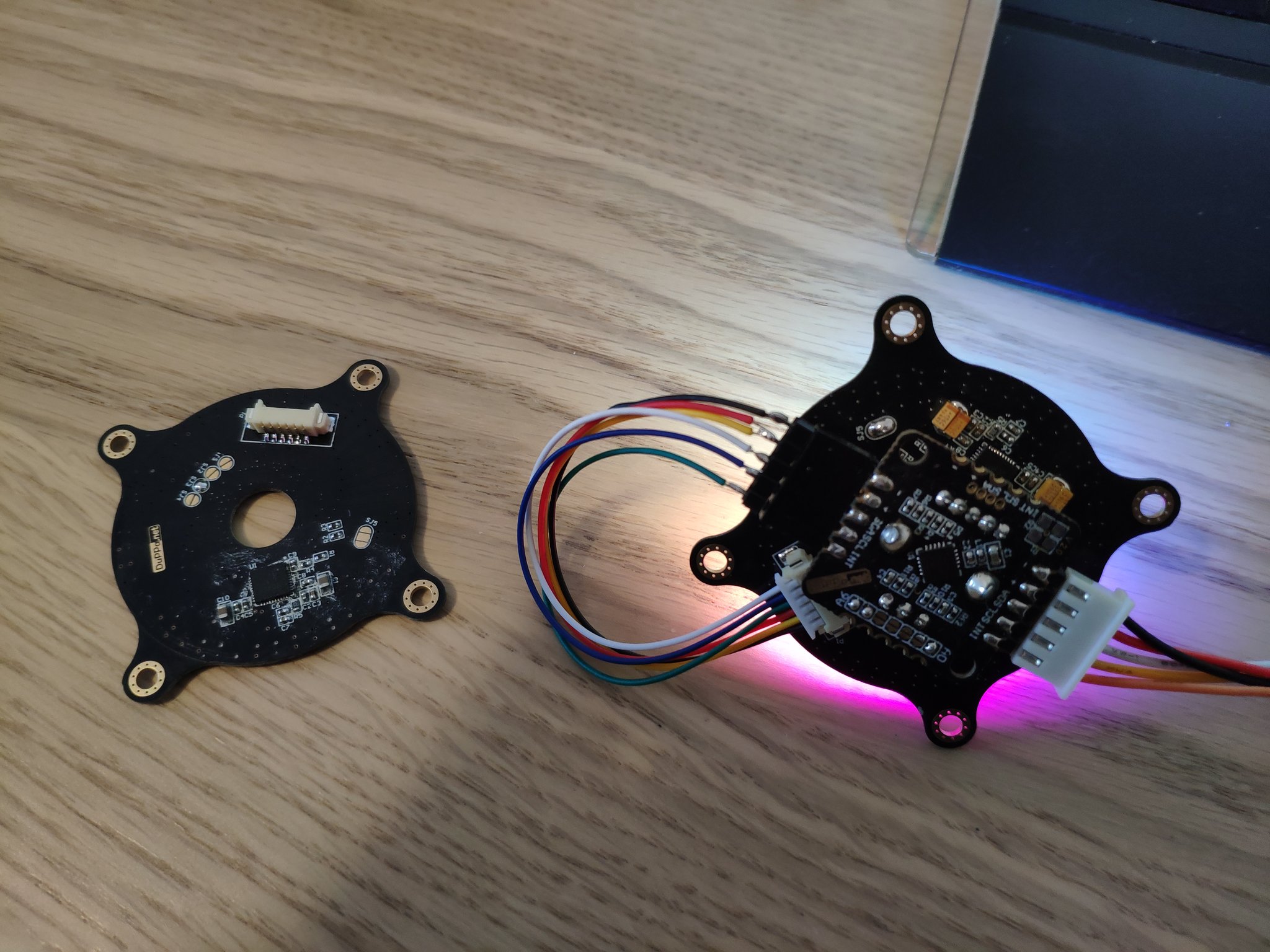
This project is a bit different because it uses a standard 2x2mm RGB LED and they are controlled with the IS31FL3737 that works using the common I2C bus.
The IS31FL3737 it's a dot matrix LED controller and support a 12x12 led matrix or 4x12 RGB matrix. But in this case, the LED are not disposed in a matrix but in a circle making the layout a bit crazy.
The board is a 4 layers PCB without exotic specification. Here the layout of the 4 layers:
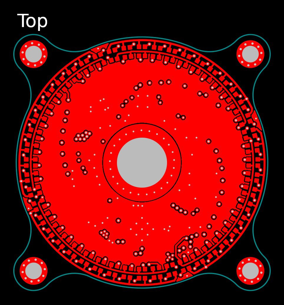 | 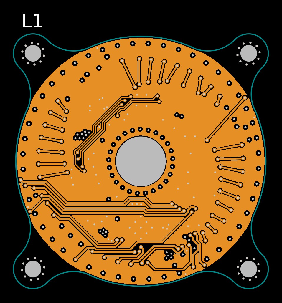 |
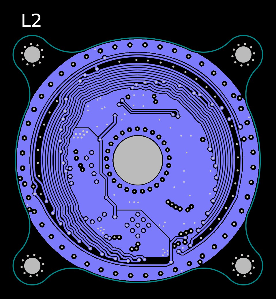 | 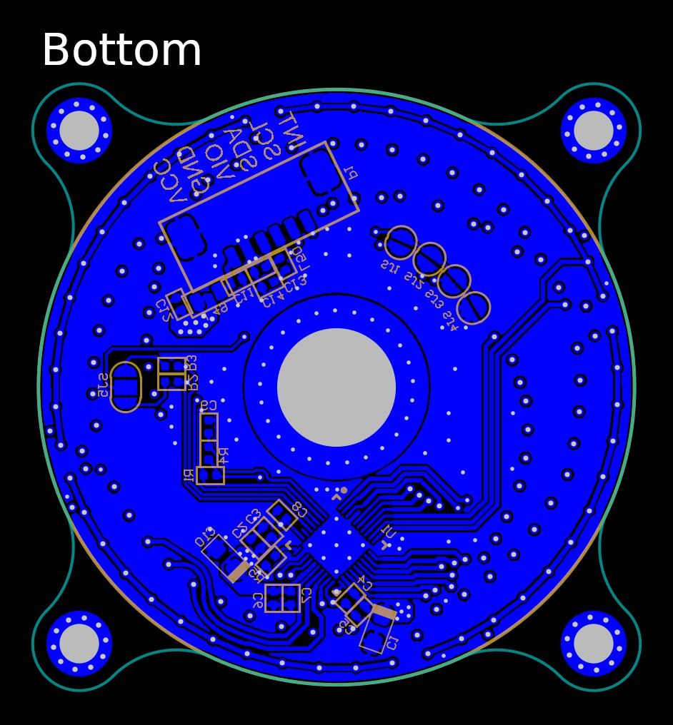 |
The IS31FL3737 comunicates with the I2C bus, and it's possible to select only 4 different addresses, this means that it's possible to connect 4 RGB LED Rings on the same I2C bus. On the RGB LED Ring, there are 4 SMD jumpers where it's possible to chose the address. There is also printed address in HEX format.

If you need more boards on the same bus, there are several I2C switches, like the TCA9548A, where it's possible to extend the addressing to more devices.
There is also another SMD jumper where it's possible to enable 4.7k pull-up resistor on the I2C bus.
The RGB LED Ring has a 5 pin JST like connector with 1.25 pitch. The pin out is the following:
| Name | Description | Voltage level |
|---|---|---|
| VCC | LED supply voltage | 2.7V - 5.5V |
| GND | Ground | 0V |
| VIO | Logic supply voltage | 2.7 - 5.5V |
| SDA | I2C data | Same as VIO |
| SCL | I2C clock | Same as VIO |
| INT | Interrupt output | Same as VIO |
It has two pins for the power supply, one is for the logic and the other is for the LED. The power can be different, for example: 3V3 for the logic and 5V for the LEDs.
We also made a simple demo video of the project using also the I2C Encoder V2.1 with a RGB encoder and the black knob. The two board are connected to the Arduino UNO with the I2C bus.

 Martin Held
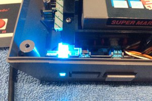
 tehaxor69
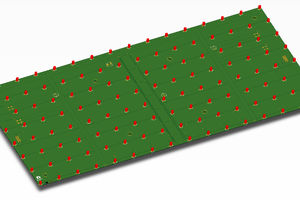
 Mirko
Mirko
 Tinkers Projects