 Circle Electronic
We will make Knight Rider car led animation with a potentiometer
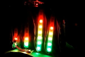
We all remember the technological car in the iconic television series Knight Rider. The most important feature of this car is that the LEDs on front of the car are constantly turn on one by one.

K.I.T.T.
For those who are new in Arduino and want to learn coding, it's time to learn how to make this animation with pot!

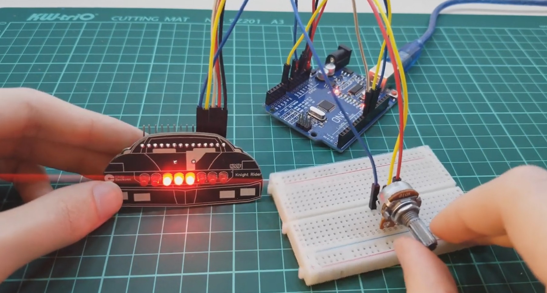
Don't mess with breadboard circuits for learning Arduino and coding, just connect the cables and start coding right now!
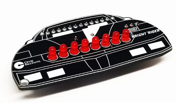
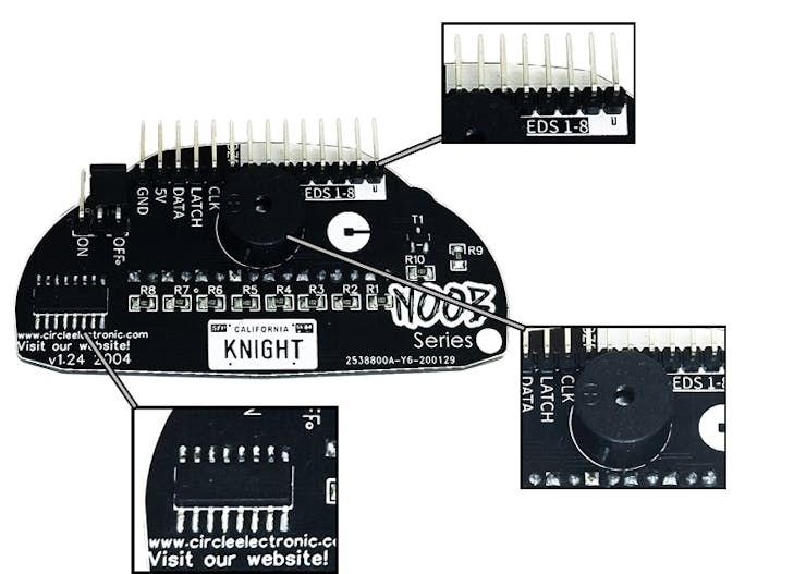
Meet the Circle Electronic NOOB Series Knight Rider!
https://www.circleelectronic.com/knight-rider
What can you do?
Knight Rider circuit LED Animation
How to make this animation with pot?
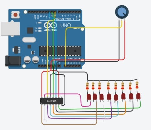
Circuit Diagram
https://www.tinkercad.com/things/6KD66LWNaAa
We will use 74hc595 Shift Register in this project.
So, how to make this animation with shift register.
#define DATA 8
#define LATCH 9
#define CLOCK 10
static int led = 0;
byte number[23] = {0b00000000,                 0b00000001,                 0b00000011,                 0b00000111,                 0b00001110,                 0b00011100,                 0b00111000,                 0b01110000,                 0b11100000,                 0b11000000,                 0b10000000,                 0b00000000,                 0b10000000,                 0b11000000,                 0b11100000,                 0b01110000,                 0b00111000,                 0b00011100,                 0b00001110,                 0b00000111,                 0b00000011,                 0b00000001,                 0b00000000                };
void setup() {  pinMode(CLOCK, OUTPUT);  pinMode(DATA, OUTPUT);  pinMode(LATCH, OUTPUT);
}
void loop() {  static unsigned long time = millis();  if (millis() - time >= 80 && led <= 22) {    time = millis();    led++;    digitalWrite(LATCH, LOW);    shiftOut(DATA, CLOCK, MSBFIRST, number[led]);    digitalWrite(LATCH, HIGH);  }  if (led == 22) {    led = 0;  }
}
This is our code to make this animation with 74hc595. We will change this to make this with pot.
We change it like it:
#define DATA 8
#define LATCH 9
#define CLOCK 10
byte number[] = {0b00000000,                 0b00000001,                 0b00000011,                 0b00000111,                 0b00001110,                 0b00011100,                 0b00111000,                 0b01110000,                 0b11100000,                 0b11000000,                 0b10000000,                 0b00000000,                             };
void setup() {  pinMode(CLOCK, OUTPUT);  pinMode(DATA, OUTPUT);  pinMode(LATCH, OUTPUT);
}
void loop() {  digitalWrite(LATCH, LOW);  shiftOut(DATA, CLOCK, MSBFIRST, number[*]);  digitalWrite(LATCH, HIGH);  }
Now we will read the data from pot
We will connect the pot middle pin to arduino analog 0 pin and read the datas
int pot=A0;
void setup() {  pinMode(pot,INPUT);
}
void loop() {  int potvalue = analogRead(pot);
}
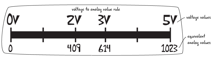
These are the data we get after making the connection. When we change the potentiometer, we read a value in the range 0-1023. We have to convert these values to 0-11.
We will use the map command to do this:
potvalue= map(potvalue,0,1023,0,11);
Now we are changing our code:
#define DATA 8
#define LATCH 9
#define CLOCK 10
int pot=A0;
byte number[] = {0b00000000,                 0b00000001,                 0b00000011,                 0b00000111,                 0b00001110,                 0b00011100,                 0b00111000,                 0b01110000,                 0b11100000,                 0b11000000,                 0b10000000,                 0b00000000,                             };
void setup() {  pinMode(CLOCK, OUTPUT);  pinMode(DATA, OUTPUT);  pinMode(LATCH, OUTPUT);  pinMode(pot,INPUT);
}
void loop() {  int potvalue = analogRead(pot);  potvalue=  map(potvalue,0,1023,0,11);  digitalWrite(LATCH, LOW);  shiftOut(DATA, CLOCK, MSBFIRST, number[potvalue]);  digitalWrite(LATCH, HIGH);  }
The final version of this code.
That's it!
Our Website: https://www.circleelectronic.com
Github Page: https://github.com/circleelectronic/Knight-Rider
Blog Post: https://www.circleelectronic.com/post/arduino-knight-rider-with-potentiometer
Tinkercad Project Link: https://www.tinkercad.com/things/6KD66LWNaAa
Knight Rider Product Link: https://www.circleelectronic.com/knight-rider
Tindie Product Link: https://www.tindie.com/products/circle/knight-rider/
Watch Knight Rider Circuit Video
 AndyMac
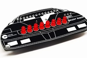
 padnest
 Siddhant Choyal