 Mike Turvey
It can be hard to visualize how the various parts come together to form a working switch. I made the following mockup to help visualize how the precise interaction of the parts and troubleshoot issues.
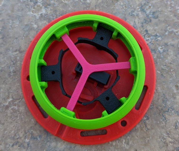
Here, you can see the Omron SS-3GP switch in its cradle (with no wires attached). The black "cap holder" is screwed down to the red base. It's easy here to see how the black "switch holder" keeps the green "switch cap" from falling off or rotating, but does so with minimal friction. The green "switch cap" is missing its top, allowing us to see in. And the pink "switch insert" inserts into three holes in the switch cap, and depresses the switch.
We've discussed tolerances some before, and this picture makes it much easier to see how the design minimizes and mitigates the effects variation in part dimensions.
In order for this switch to perform well, the height of the pink "switch insert" must be precisely controlled to within about 0.1mm to 0.2mm. And we have to reliably hit that when some of these parts with layer heights of 0.2mm.
Minimize Variations
First, to minimize the variations, it's important to consider how a 3D printer manufactures a part. First, it lays down an initial layer, generally smooshing that first layer into the print bed. The print bed itself will also have slight variations. Combined, this means that the first layer (or maybe even first few layers) of a part can be expected to have fairly high variation in thickness.
Another place where you'll see a lot of variation is in overhangs. There will be some drooping in overhangs, and the amount of drooping can vary with temperature, filament, printer, speed, cooling, support, etc.
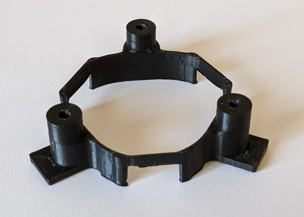
Where we can find reliable, precise tolerances is between horizontal "top" surfaces on a part. Let's look at the "cap holder" for example. It is printed upside down, and the critical dimension (where it mates with other parts) is on two "top" surfaces.
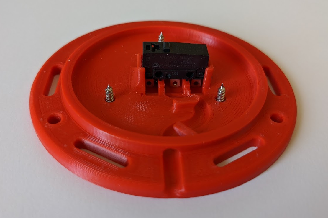
With the red base, the critical dimension is on the top surface-- where the cap holder feed reside and where the SS-3GP microswitch sits.
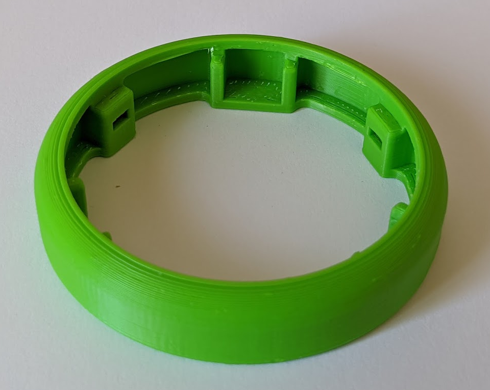
With the green "switch cap," the critical dimension is the top surface that mates with the cap holder, and the pockets that hold the pink "switch insert." The pockets have both a "top" surface and an overhang. The variance in the overhang is largely suppressed because of another trait of the overhangs: they're a bit soft and sponge-like. The pink "switch insert" has a slight wedge to it, and the softer overhang helps to press the "switch insert" flush against the top surface of the pocket.
That leaves the switch insert, which is also printed upside down. That means that its top surface is being pushed against the top surface of the pocket on the green switch cap. The other critical surface is where the "switch insert" presses against the microswitch. Again, this is a top surface when printed, and so has high precision.
Of course, the last piece in all of this is the Omron SS-3GP switch itself. And it's safe to say that all of its tolerances are significantly better than the 3D printed parts.
Mitigate Variations
Now that we've done all we can to minimize variations, we now have to accept the fact that nothing is perfect and we'll have some variation and have to handle it somehow.
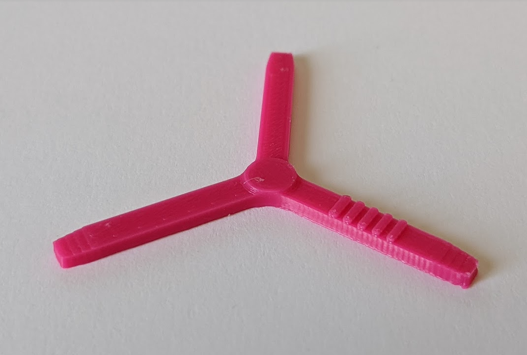
Early in the design process, I knew that I wanted the ability to have a small, quick-to-print component that would be easy to replace that could be used to "shim" to adjust for variations in tolerances. That's where the "switch insert" comes from. Each switch insert takes less than 10 minutes to print, can easily be swapped out, and can be printed with different thicknesses in 0.1mm increments.
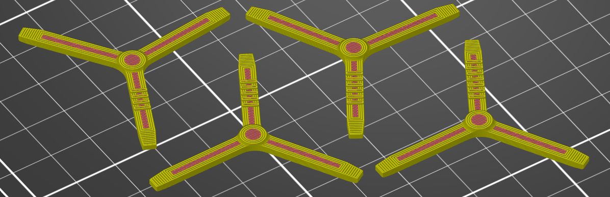
Above, you can see 4 different inserts, where the center "nub" has a height ranging from 0.4mm on the left to 0.7mm on the right. In order to identify the height of a given insert, I have added stripes to the model that indicate which variant a given part is (you'll see 4 stripes on the left insert, up to 7 stripes on the left insert).
The Results
I've been surprised at how well this has worked. Of the first 50 or so switches I've printed, every single one has required the 0.6mm switch insert. When I developed a different style of switch cap (I'll talk more about it in another log), I found that I always had to use a 0.5mm insert for it (again, for every one I printed), even though the critical measurements for it shouldn't have changed between the two cap designs. This tells me that the random error is effectively negligible, and the systematic error is highly repeatable. This is fantastic, as it makes manufacturing a large batch much easier/ faster. You effectively don't have to worry about disassembling switches to swap out with a different insert, which would be rather time consuming.
Discussions
Become a Hackaday.io Member
Create an account to leave a comment. Already have an account? Log In.