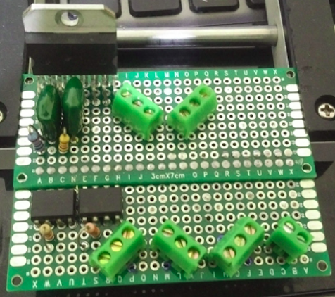
The last time I said that I changed my mind about power stage, this is why... I used 4 MOSFET D-PAK STD22NM20N, a spare perfboard from those that PCBway always give away and other basic components.
Then I realized that will be difficult to put a heat sink on this and surely I will need a heat sink for each bridge... but while I was thinking about it I remembered that I have some L298HN on my parts bin. Those IC can control up to two direct current motors on both directions each one, two of them can control three HDD actuator arm, at 15 pin each IC I can use prefboard without problems also the horizontal package ease the mount of a heat sink even if I can place both IC appropriately both can share the same heat sink.
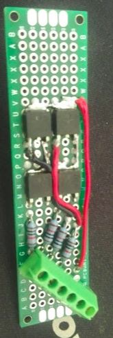
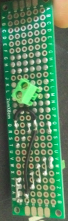
First I build only the minimum to control one VCM from opto isolators to L298HN and do some test, and this is the result.
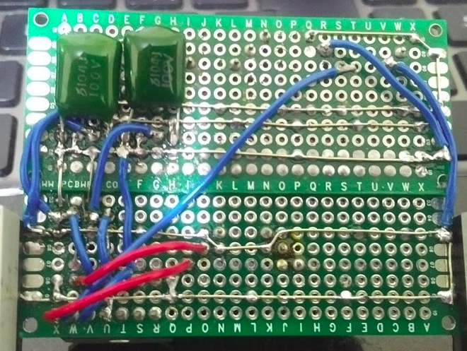
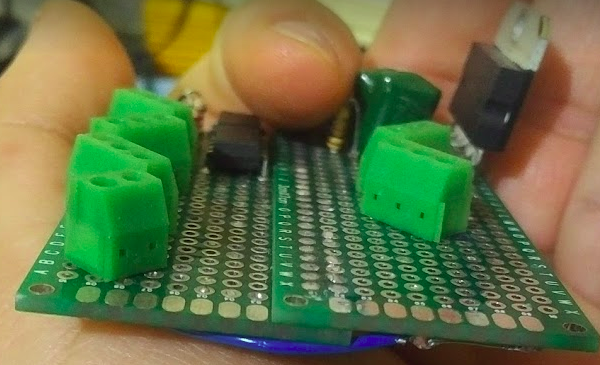
If you see I soldered two perfboards togheter, in the end the area was much smaller than having used H-Bridge option, Optocouplers are 6N137. At this point the circuit is incomplete and has this schematic:
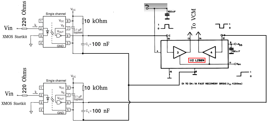
OK first I need to say that I've been a little lazy on this schematic, I used images from the datasheet of both IC I trust it won't cause much problem... So the schematic in part isn't the implemented circuit, the L298HN on the schematic show the full bridge composed of amplifiers 3 and 4, the implemented circuit used 1 and 2, the only differences are on pin used on the L298HN to use the amplifiers 1 and 2 (inputs and ouputs) check the datasheet for more details, also there is no sensing resistor on implemented circuit.
I test the circuit with this conditions:
- Optocouplers Vin 3.3V
- Optocouplers Vcc 5V
- L298HN power suppy Vs 7V
- L298HN Logic supply Vss 5V
- HDD VCM connected on output of amplifiers 1 and 2
Test went well, and the HDD actuator arm move on both direction as Vin was a logic high on one optocoupler and low on the other and viceversa.
I have to say that just before I start the circuit build I tested all the 6N137 optocouplers on a breadboard and six of seven work, six is the number that I need, I don't have more 6N137 I must be very carefully to not damage any.
Now why 7V for L298HN Vs? the reason is that as I stated on past logs I want to supply the VCM with 4.5V - 5V, so the datasheet for L298HN says this:
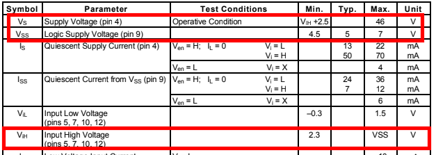
and this:

The LN298HN has it's dual H-bridge based on BJT, if I want Vl = 4.5V to 5V then I need to apply a Vs that by subtracting the Vce drop from on transistors susch that Vl will be on the range, then from datasheet Vcesat = 1.8V to 3.2 at 1A current, on my case are 450mA to 500mA, so with Vs = 7V then Vl = 5.2V to 3.8V if Vl is above or under the range of 4.5V to 5V then I simply adjust Vs.
With the first try (Vs = 7V) the measured Vl on the output with VCM connected gave me 4.5 Volts, it work even with Vs under the minimum, datasheet says Vsmin = Vih +2.5V and with Vih = 5V Vsmin = 7.5V... but it works excellent!!! Sorry there is no photo of this :¬(, now I can continue...
In the next update I will show the power stage circuit completed and tested (I hope).
Discussions
Become a Hackaday.io Member
Create an account to leave a comment. Already have an account? Log In.