Close
0%
0%

Component Tester in a Keychain

Test any electronic component with this pocket component tester

Similar projects worth following
Component Tester in a keychain is a universal testing device for electronic components with three or lesser pins. It can automatically detect the plugged-in electronic component and measure the desired component parameters without having the user to manually select the component type, unlike the multimeter. It is based on the popular AVR TransistorTester.

It measures approximately 6cm x 3cm and is a one-button device that is capable of testing components such as resistors, capacitors with their ESR values (if any), inductors, diodes, transistors (BJTs, UJTs, and PUTs), FETs (JFETs and MOSFETs), Thyristors, TRIACs and more. Additionally, a function generator is available at Test Pin 2. To make it look a premium tester, I ordered the PCBs with a matte black soldermask from PCBWay, who also sponsored this build.

Being an electronics engineer, I always wanted to have a portable component tester, which could test every electronic component out there. In 2016, I built myself a Component Tester based on AVR TransistorTester by Markus F. and Karl-Heinz Kübbeler. This summer, I thought, can it be made pocket-sized? Since my last version was quite big and difficult to carry around.

I started redesigning the PCB with SMD components and an OLED display since it is small, lightweight, and consumes less power. I wanted to retain banana jacks since they offer testing device a robust look and makes it more compatible. Say, I can use SMD tweezer probes for testing SMD components or say I can use alligator clips or anything else. I am no longer limited to plug in my part to the tester to test it. 

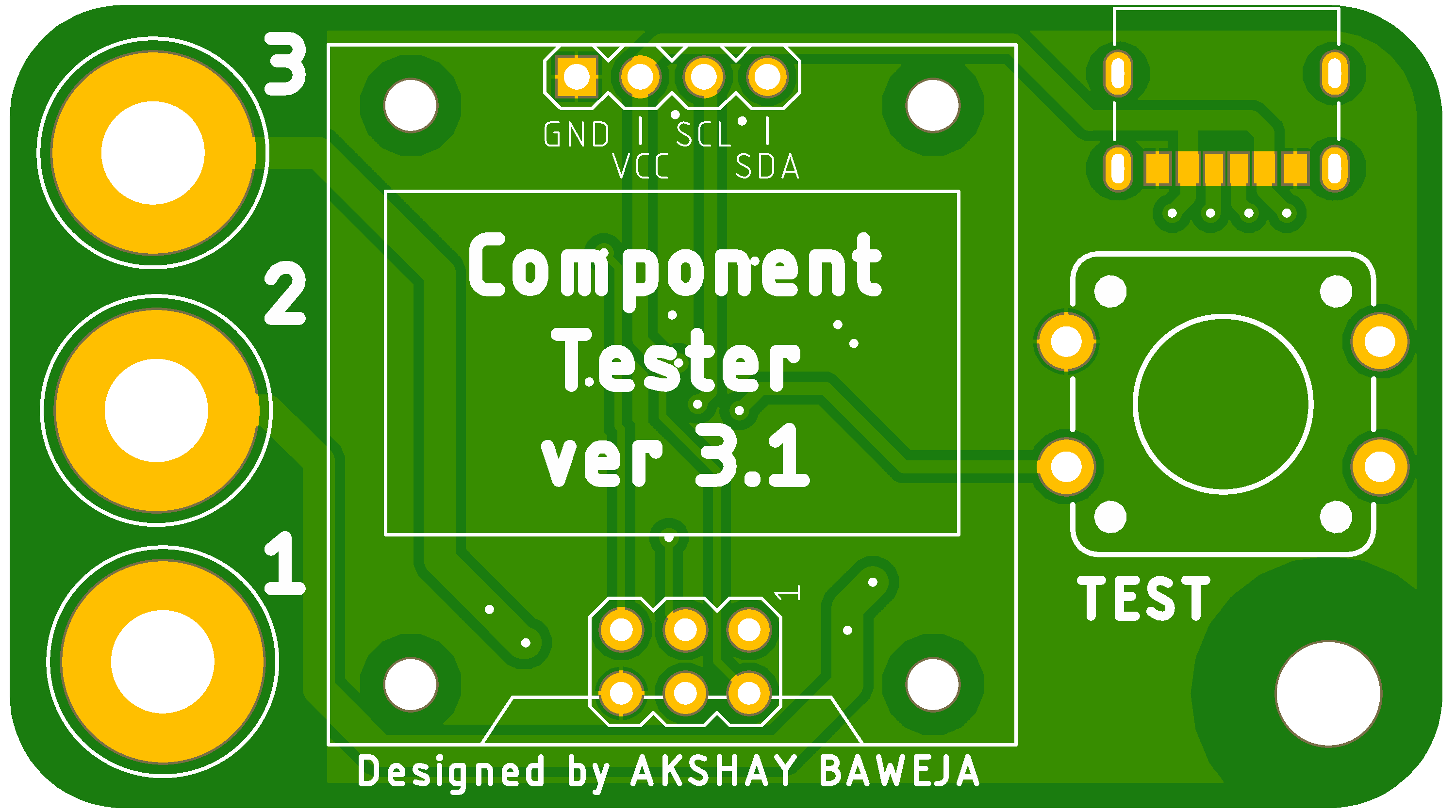
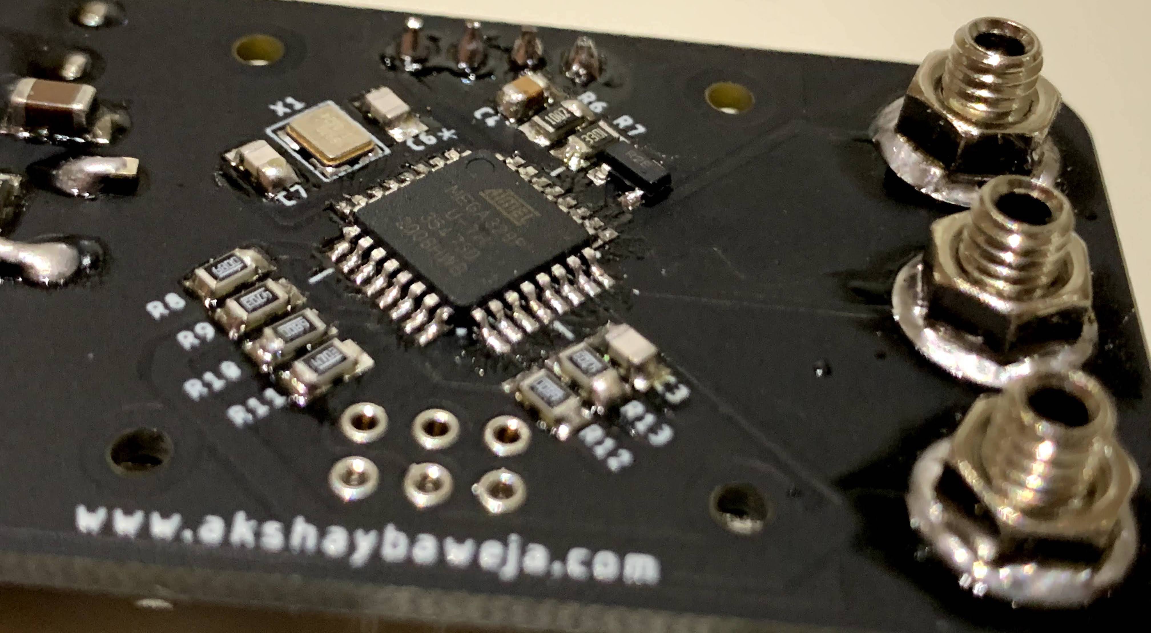
After spending a few hours fiddling around the PCB layout, I managed to bring it down to as small as 58mm x 32mm (2.28in x 1.26in). Pretty little, right? To make it a fit as a keychain, I added a punch hole on the bottom right corner of the PCB so you can put in a keychain ring or a fancy lanyard. The tester boots up as soon as you power it up via USB C.

Once you connect the component, press the button next to the display to begin testing. Since it has only one button, it makes it easier to use and makes it look less complicated as an electronic tester, which may appear very complex to use at first to many users. Also, to navigate to menu the user just needs to double press the button once a component has been tested or a "No component screen is shown".

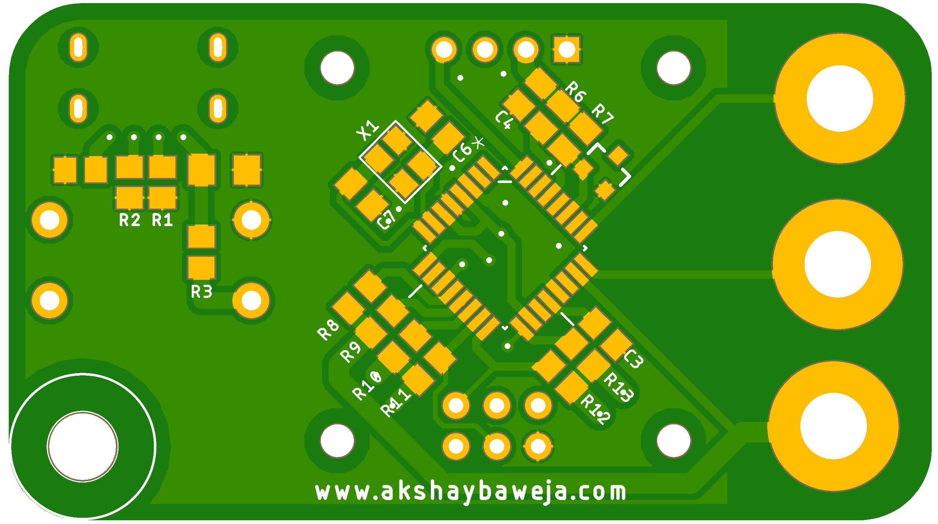
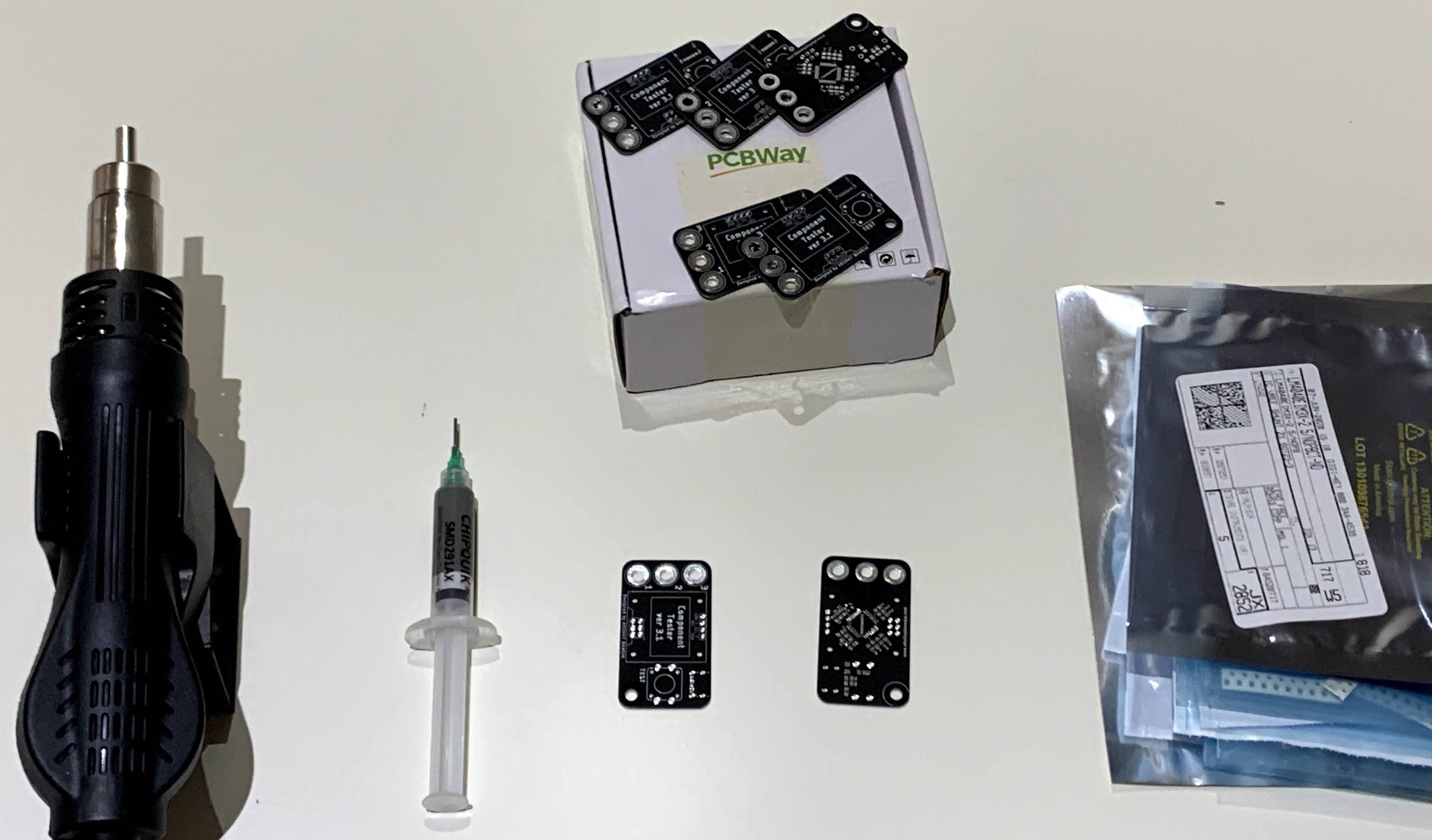
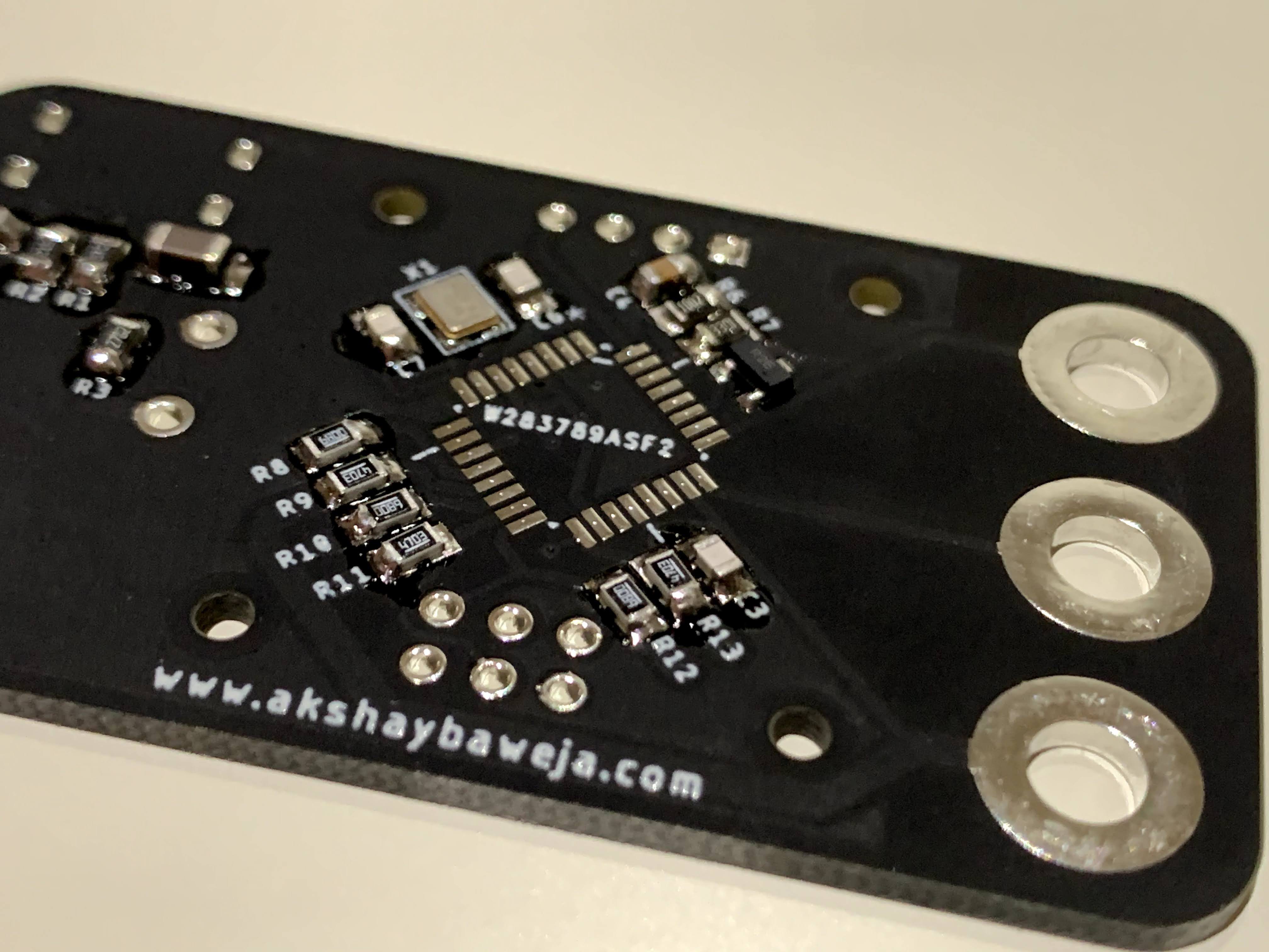
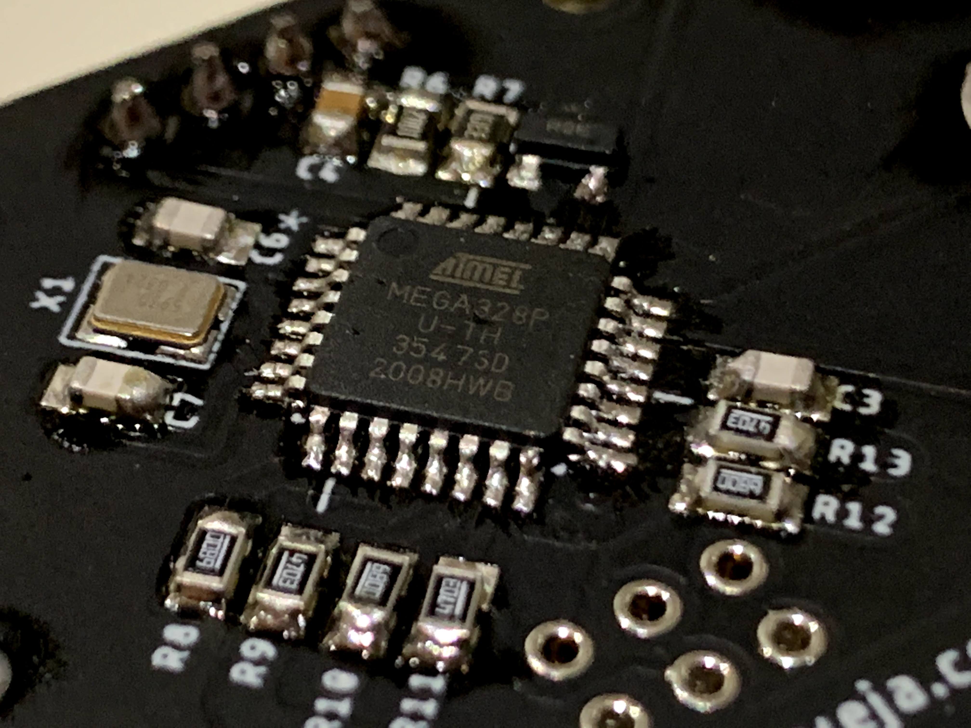
I used 0805 package components for the tester since they are the smallest components one can solder by hand and can be eyes directly without a magnifying glass. I used solder paste along with a hot air reflow tool to solder in the components.


A HUGE THANKS TO PCBWAY FOR SPONSORING THIS BUILD

PCBWay offered to step in and helped me to support this project. They also offered their PCB services for the build. I got PCBs in premium matte finished soldermask which just upgrades the overall build quality of the tester. They offer 10 custom PCBs for as low as $5 with a wide array of choices such as soldermask colors, surface finishes and much more. The turnout time for PCBs was amazingly fast. I got my PCBs delivered in 3 days from the day I placed an order. They also examine each PCB design manually before manufacturing so you do not receive any defective PCBs. I recommend trying their PCB service if you need one.

Schematic.pdf

Schematic for Component Tester (Keychain)

Adobe Portable Document Format - 60.55 kB - 06/20/2020 at 09:36

Preview
Download

TransistorTester.hex

Firmware File

hex - 87.80 kB - 06/20/2020 at 09:34

Download

TransistorTester.eep

Firmware File

eep - 2.45 kB - 06/20/2020 at 09:34

Download

GERBER_FILES.zip

Gerber Files for PCB Production

Zip Archive - 123.49 kB - 06/20/2020 at 08:20

Download

  • 1 × CAP CER 0805 0.1UF 100V X7R C0805C104K1RECAUTO
  • 1 × CAP CER 1000PF 50V C0G/NP0 0805 C0805C102J5GACTU
  • 3 × RES SMD 470K OHM 0.1% 1/4W 0805 ERJ-PB6B4703V
  • 1 × ATMega328 MCU 8BIT 32KB FLASH 32TQFP ATMEGA328P-AUR
  • 1 × LM4040 / IC VREF SHUNT 2% SOT23-3 LM4040EIM3X-2.5/NOPB

View all 18 components

  • 1
    PCB Fabrication

    The first step in building the keychain component tester is getting the PCBs fabricated for it.

    You can find the Gerber files for PCB manufacturing under files section or on project's GitHub repo. 

    I used PCBWay's Prototyping Service for getting my boards fabricated. They offer great quality boards for a very low and affordable price. They also offer a variety of solder mask options to try. I got my boards manufactured with Matte Black solder mask which makes the PCBs look very premium. 

    Component Tester KeychainAlternatively, you can click the left image to order PCBs directly from PCBWAY. You can also add an SMD Stencil from them for just $10.

  • 2
    Ordering and Soldering Components

    The list of components in the components tab provide a detailed information on components you need to order to get started with the assembly process. The components have a manufacturer's reference number so you can hunt the parts hassle free.

    I usually start by soldering resistors first followed by capacitors and then moving onto bigger components like microcontroller, buttons, OLED Display, etc. It makes life a bit easier.

    ⚠️ REMEMBER TO ALIGN MICROCONTROLLER'S DOT WITH DOT ON PCB (NEAR C6) BEFORE YOU BEGIN SOLDERING IT ⚠️

  • 3
    Adding banana sockets

    Lightly tin the base of PCB where banana socket goes into and slide in the socket as shown. Once you slide in put  a bit of solder between the little space between hex nut and the base. This will ensure a string connection and give you better and more accurate testing results.

View all 5 instructions

Enjoy this project?

Share

Discussions

zwaini966 wrote 03/29/2022 at 05:03 point

Hello, what kind of IDE development environment is used for this?

  Are you sure? yes | no

Martin Stejskal wrote 03/10/2022 at 20:35 point

I just build it and it works like a charm! However I noticed few things during build.

 The silk for C2 and C5 is not on PCB. It is possible to guess it though.  Regarding resistors, only accurate needs to be 470k Ohm and 680 Ohm. Others can be 5% or even less accurate. I would recommend to add 10nF between RESET and GND. It will help to keep MCU in noisy environments (avoid reset). Also fuses seems to be incorrect. According to fusecalc, the oscillator settings is set to internal 8 MHz oscillator not the external XTAL. So correct fuses shall be "-U lfuse:w:0xff:m -U hfuse:w:0xd9:m -U efuse:w:0xfc:m". I tried that settings and seems to be working well.

  Are you sure? yes | no

Zxx-Eric wrote 10/15/2020 at 06:21 point

This is great. I tried to do two, using one 10nF and one 22uF according to your calibration method, and found that the measured value of the component is equal to half of the actual value. Please tell me what may have gone wrong?Better add a menu inside the use method, looking forward to your reply, thank you

  Are you sure? yes | no

Justin Davis wrote 09/28/2020 at 23:45 point

This is great!  I think to make it pocket-proof though, it needs some kind of case.  I can just imagine all the rubbing on those tiny SMTs.  3D printing?

  Are you sure? yes | no

Akshay Baweja wrote 10/10/2020 at 13:22 point

Hey, I am working in a TPU 3D Printed case... will be up soon :)
Alternatively, you can spray coat it with a thick electronics waterproofing solution.

  Are you sure? yes | no

dirk.backvis wrote 07/06/2020 at 11:43 point

hi is there a arduino code for this project?

  Are you sure? yes | no

Akshay Baweja wrote 07/06/2020 at 12:56 point

Hey,

Sorry Arduino Code is not there for this project. But you can hack and use a UNO to make this.

  Are you sure? yes | no

dirk.backvis wrote 07/06/2020 at 14:18 point

so in the code transistortester.hex or transistortester.eep is the source code that the ATMega328 MCU will use to get the right messurament for the component that you put in the 3 borns, or am i mistaken?

  Are you sure? yes | no

Akshay Baweja wrote 07/07/2020 at 16:37 point

yes right. You need to upload both the files (.hex and .eep) to your MCU

  Are you sure? yes | no

meahdi wrote 07/01/2020 at 13:21 point

Hi

I download all Files but hex and eep file corrupted. all of file filled white 1 to 0 and a to z characters and repeat many time !

How can i get true file ?

  Are you sure? yes | no

Akshay Baweja wrote 07/01/2020 at 14:05 point

Hey,

Hex files are HEXADECIMAL ENCODED files. HEX files and EEP files are not human readable. Once you build this in the manner described. You can use a serial programmer and just upload those files. You microcontroller will read them and perform required tasks.

Do you mean you want actual code files?

  Are you sure? yes | no

meahdi wrote 07/01/2020 at 16:16 point

I know about HEXADECIMAL encoded files

May I have actual code files

can i program this file directly to ic by programmer?

  Are you sure? yes | no

Akshay Baweja wrote 07/02/2020 at 04:59 point

Yes you can directly burn the hex and eep files to ATMega328.

I'll upload the code files soon.

  Are you sure? yes | no

meahdi wrote 07/02/2020 at 05:14 point

Great thanks


  Are you sure? yes | no

Akshay Baweja wrote 07/06/2020 at 12:55 point

Hey,

Updated source code on GitHub

  Are you sure? yes | no

Martin Stejskal wrote 06/27/2020 at 07:56 point

What are practical measurable ranges for resistors, capacitors, inductors?

  Are you sure? yes | no

Akshay Baweja wrote 06/27/2020 at 09:35 point

Hey,

Following are the ranges -

Resistor Range: 0.1Ω – 50MΩ

Capacitor Range: 25pF – 100000uF

Inductance Range: 0.01mH – 20H

  Are you sure? yes | no

Similar Projects

Does this project spark your interest?

Become a member to follow this project and never miss any updates