 John Opsahl
The Problem
"Commercial fluid warmers are either cost prohibitive in many contexts or not available for purchase" (Field Ready Fluid Warmer Open Challenge, Hackaday Prize 2020).
The Solution
An IV fluid warmer solution that incorporates all industry standard safety features and solves the difficult cost and sourcing challenges encountered when constructing this device anywhere in the world.
The Impact
- A safe, low-cost IV fluid warming solution that is accessible worldwide.
- A reduction in the cost of commercially available fluid warming solutions either by market pressure from a lower cost option or by adoption of the OpenFluidWarmer approach.
- A proven product development path for open-source electromechanical medical devices.
Hackaday Prize 2020 Judging Criteria
i. Concept. The OpenFluidWarmer has the potential to become one of the world's first open source life-critical medical devices. Achieving this status requires an innovative new take on IV fluid warmer design. It must incorporate all industry standard safety features and solve the difficult cost and sourcing challenges involved with constructing this device anywhere in the world.
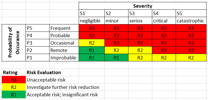
ii. Design. From product requirements to FMEA and competitive analysis, all design documents are shared in the "Files" section of this project. In addition, significant design efforts and milestones are documented in the "Project Logs". The design will undergo rigorous verification before being released to the public. A user manual will provide instruction on operating procedure, safety hazards, maintenance, and troubleshooting.
iii. Production. Reproducibility is at the core of the OpenFluidWarmer design. Through common off-the-shelf components, widely accessible fabrication techniques, and a flexible design that can accept multiple alternative components, the OpenFluidWarmer will solve the cost and sourcing challenges encountered when constructing this device anywhere in the world. An assembly manual will guide users step-by-step through the assembly process.
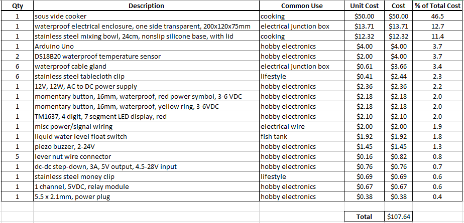
iv. Benchmark. A competitive analysis was performed to understand how the OpenFluidWarmer compares to commercially available IV fluid warmers (see "OpenFluidWarmer_competitive_analysis" in the "Files" section of this project). The most significant findings from the competitive analysis are discussed in this "Competitive Analysis" project log. The price and quantity of each item used in the device is detailed in the "OpenFluidWarmer_BOM" document in the "Files" section of this project.
v. Communication. All significant project efforts have been documented on the OpenFluidWarmer Hackaday.io project page so others can quickly become familiar with the current design and the processes used to develop it.
Development Milestones
- Initial system architecture and cost study, complete
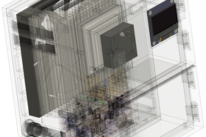
- Initial mechanical design, complete
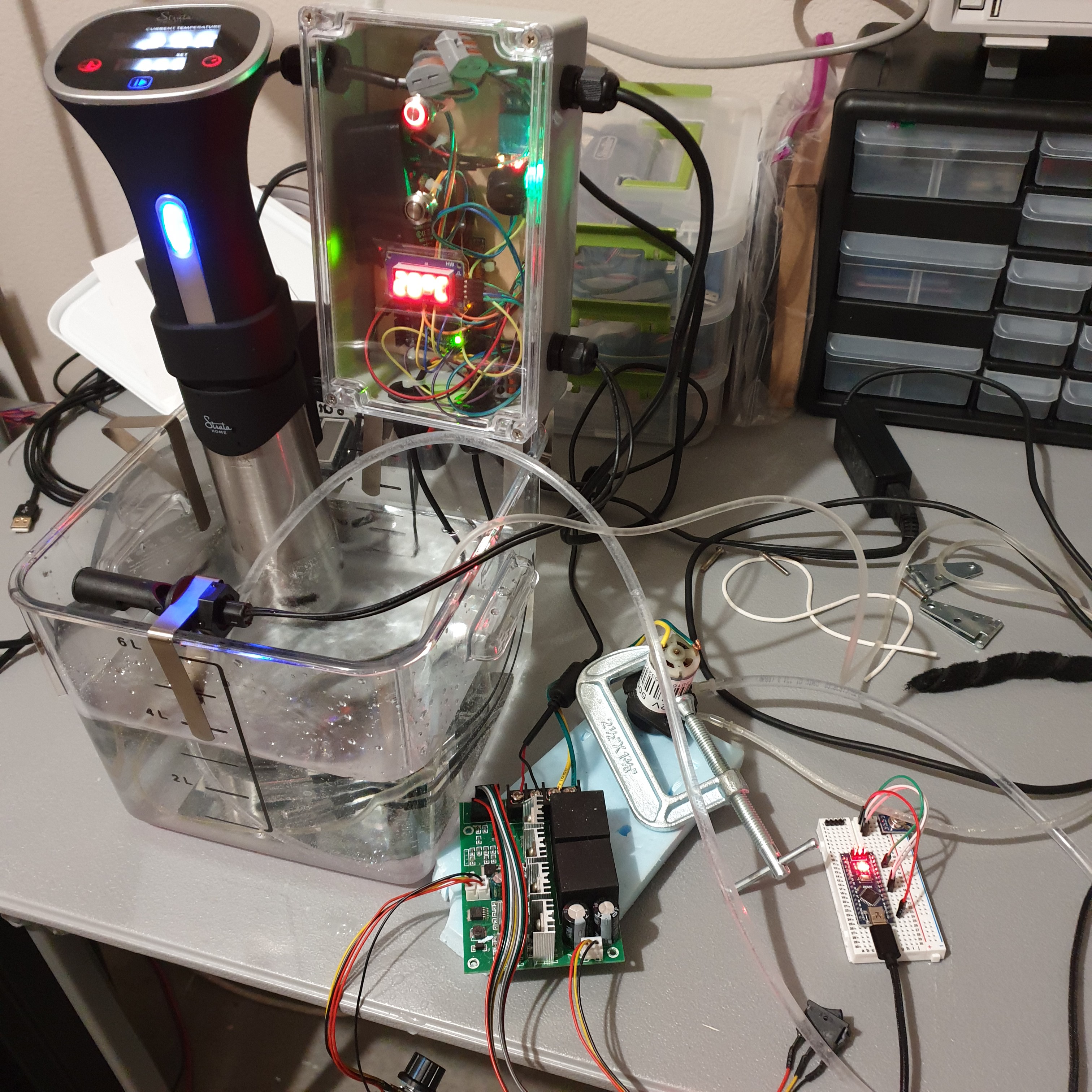
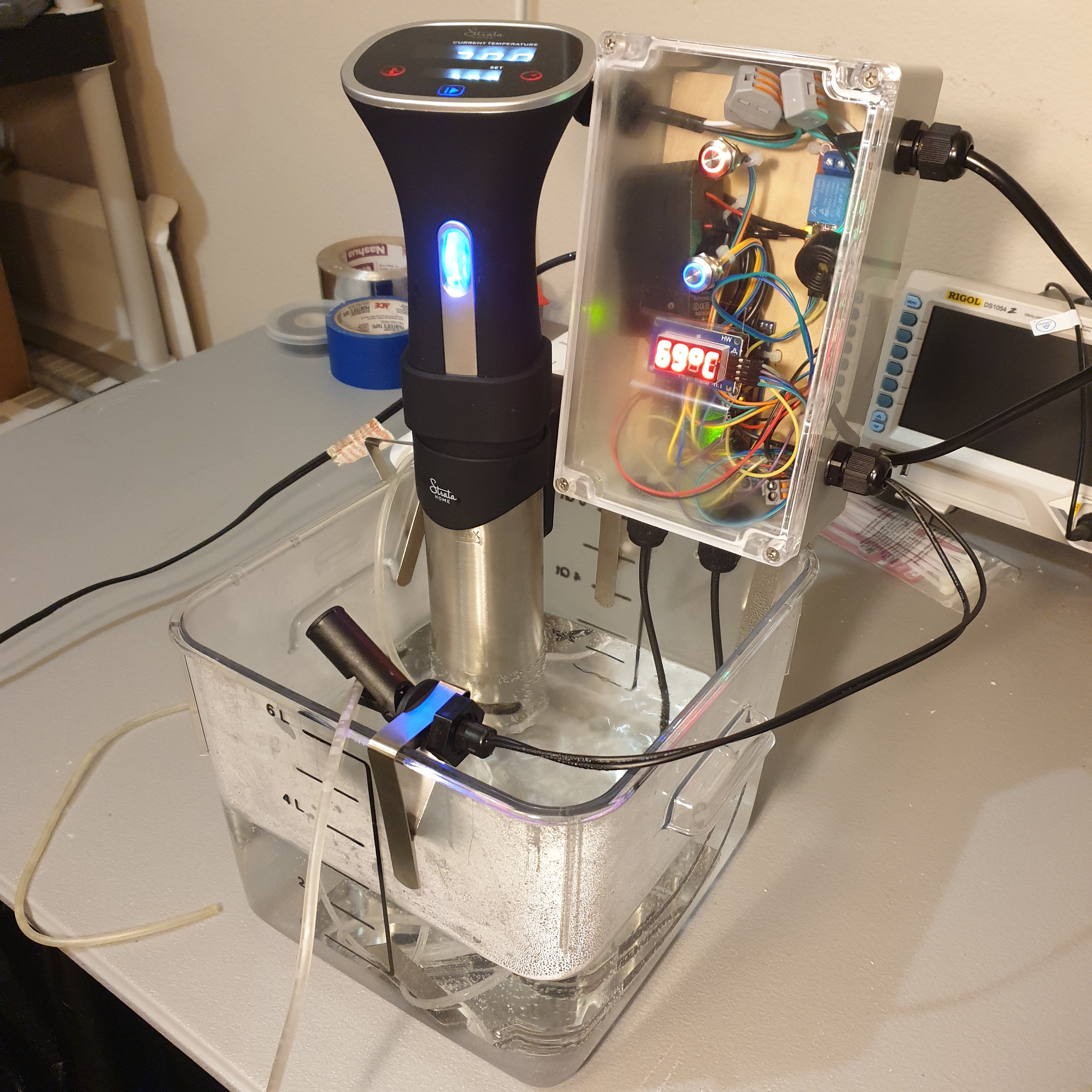
- Heat transfer proof-of-concept prototype, complete
- Gen 1 prototype code development, complete
- Gen 1 prototype testing, complete
- Gen 2 heat transfer approach, complete
- Gen 2 system architecture, complete
- Gen 2 code development, complete
- Gen 2 prototype testing, complete
- Field prototype, not started
- Field prototype testing, not started


 Jung Hoon Lee
 Tom
Tom
 Gabriel Faleiro
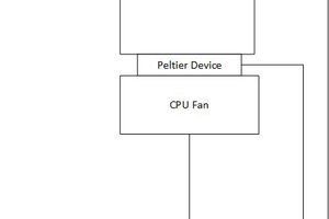
 parkolay
Hey there. I wanted to make sure I fully understood everything before commenting.
With being a class IIb device and hitting the other regs makes QA/QC kind of straightforward.
You'll need to quality control the firmware, which means, among other things you'll need version control, commit signatures, a bug tracking system, and release testing.
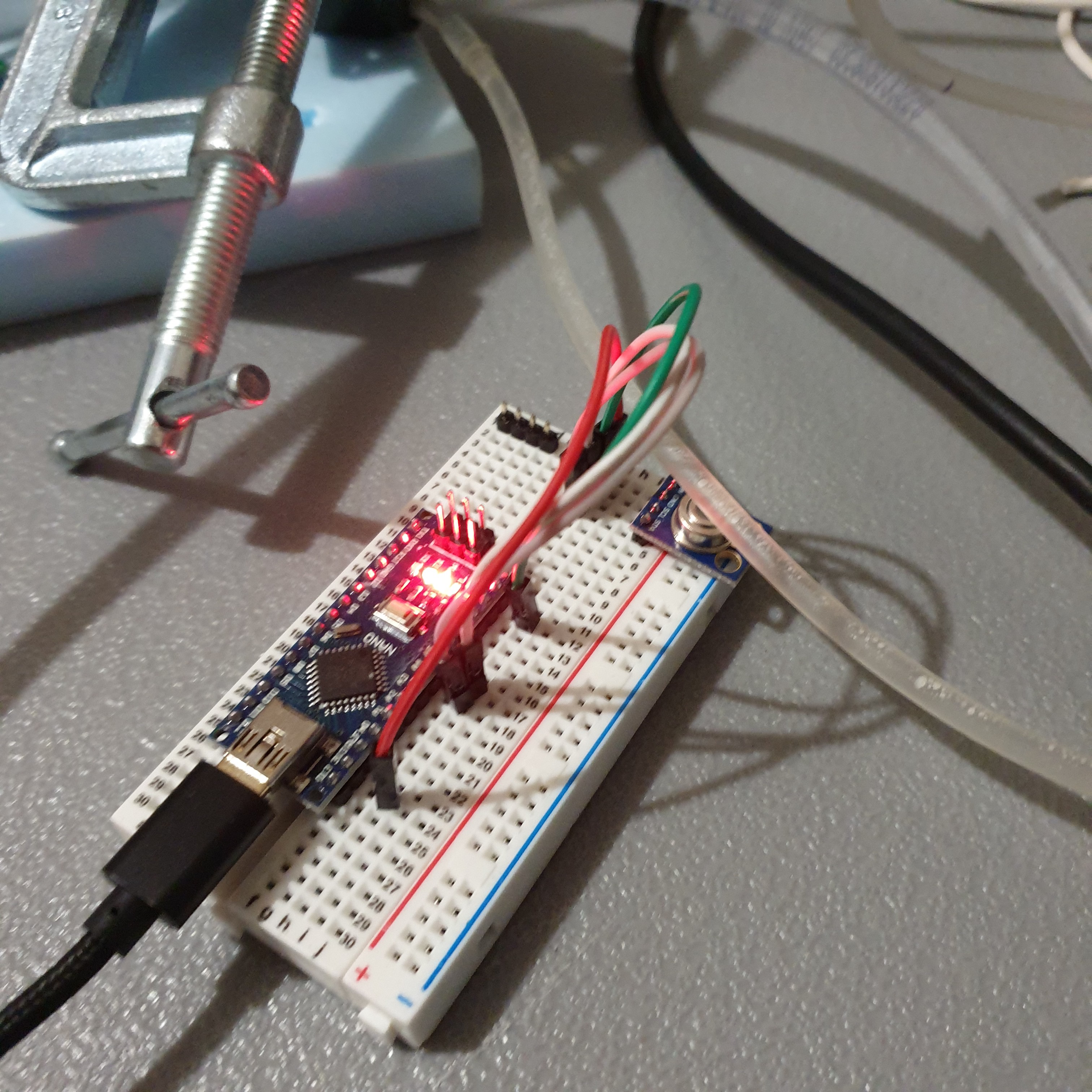
For the firmware release testing you'll need to basically trigger each of the code paths and make sure they work as intended. This means causing each of the 9 faults and verifying the lights and buzzer plus the normal operation ping. The rest of the testing can be saved for the finished product testing. For firmware testing you can use "tricks" such as a resistor or controlled current to simulate temperature, but for product testing you'll need to include the assembled thermistor in the loop.
For each produced unit you'll want to do QA that consists of build integrity (seal condition, etc) as well as functional testing. For functional testing you'll want to ensure that it is able to meet the product specs (i.e. warm from 4deg to 36deg in x seconds, warmup time, flow rate etc). It sounds like a lot but you could trigger the hot/cold with ice cubes and hair dryer. Getting it at exactly 42c etc. is only necessary for the firmware testing, for finished product testing you can overshoot.
You might want to build a testing rig that can test many units at once to not cause a bottleneck in production. Probably 5 is a good minimum but 6 is a very divisible number for handling stock requests on the fulfillment side.
To test warming and flow you could use some kind of analogue. I'm not aware of if there is any official analogs for blood but I'd guess some sort of formulation of water and baking soda could do it. You'd have to of course match the specific heat and viscosity.
QC for finished product consists of verifying QA paperwork is completed properly and signed off, and visual inspection. Visual inspection should be thorough and track things that wouldn't even affect operation such as scratches or extraneous sealant or solder, etc. You should have a library of common defects and their severity, with example photos of each kind of defect. One allowable severity is "cosmetic" and doesn't necessarily fail the QC (unless you want it to).
Assemblers and inspectors should have documented training (a signed log that once a year or release version or whatever is reasonable, they have reviewed the product design manual / inspection procedures)
You should also include in the product documentation a suggested QC for incoming materials, although it may need to be customized to suit individual material choices and sources.
One thing you may want to consider is putting a lifetime operating hours counter in the unit. I'm not sure if the Nano has an RTC or nonvolatile storage but they can be added for very little cost.
I understand you want parts to be easily available too but thinking as a user it might be nice to have a version of the product which uses an LCD screen with full operating status, even if it makes IP54 more difficult. If I was operating one of these things I'd want to see Lifetime power-on, time since power-on, current temp, Alarm history log, estimated flow rate, battery remaining, etc.
Adafruit/digikey has a display for only $10 surprisingly ( https://www.adafruit.com/product/4383 ). Might also be able to double as non-volatile storage.
That's probably plenty to start. Hope it helps! Each part can be expanded on in great detail when the time comes.
Oh one more thing you probably want to test at least once, having several fully charged batteries ready then operating the thing for many days on end without interruption and make sure it doesn't overheat the Nano or something. In a variety of ambients (like a desert field hospital). You just know someone will use it in this way...