 Mattias
System Overview
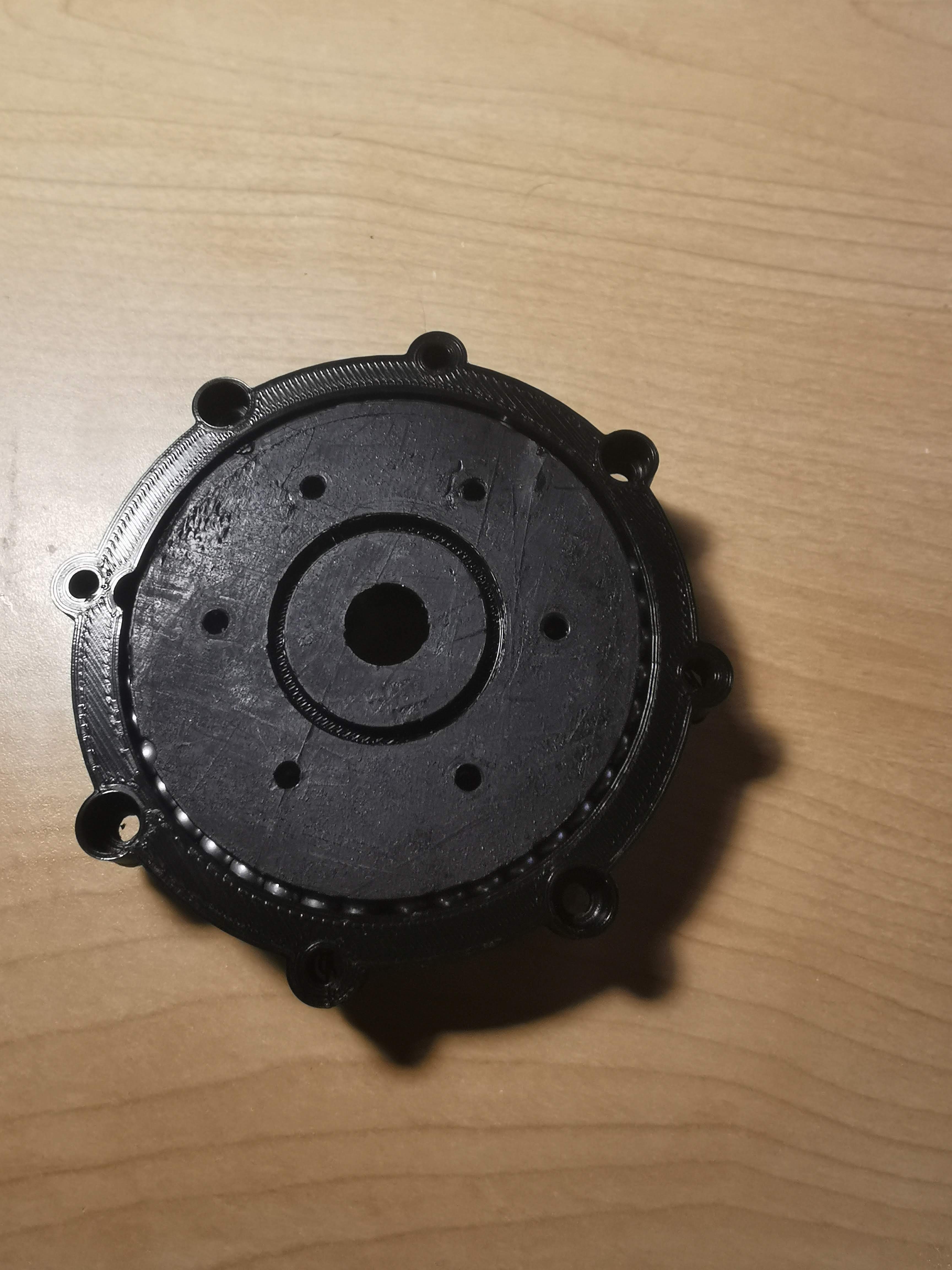
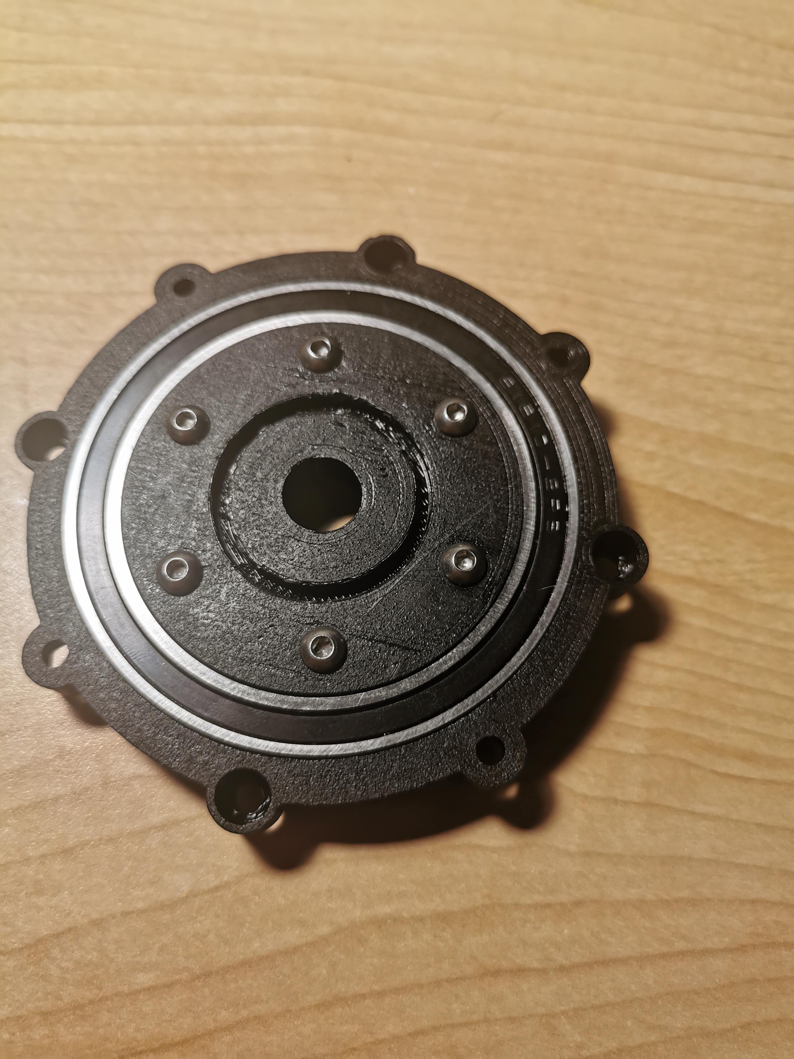
The Actuators
The whole system is designed around a custom designed planetary gearbox for the NEMA 11 and NEMA 17 motors. The actuators for the NEMA 17 motors are geared down with a ratio of 28.4:1, while the smaller actuator for the NEMA 11 is geared 19:1. These can be found here:
- Large Actuator: https://www.thingiverse.com/thing:4428749
- Small Actuator: https://www.thingiverse.com/thing:4423264
The robot uses 3 of the large actuators for the NEMA 17 motors on joints 1, 2, and 3, and a single small actuator for the NEMA 11 motor on the joint 4 (for the end-effector).
The Structure
Once the actuators are assembled, they are connected to each other with the list of 3D printable parts. It is a simple design around the actuators and they shoulder, forearm, and base joints can easily be fastened together (.STL files attached to the project).
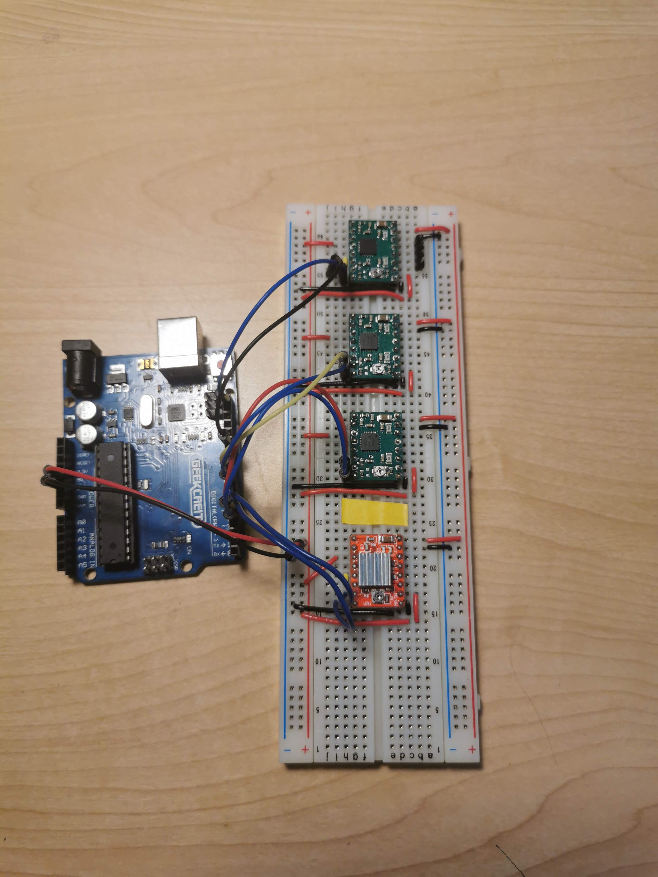
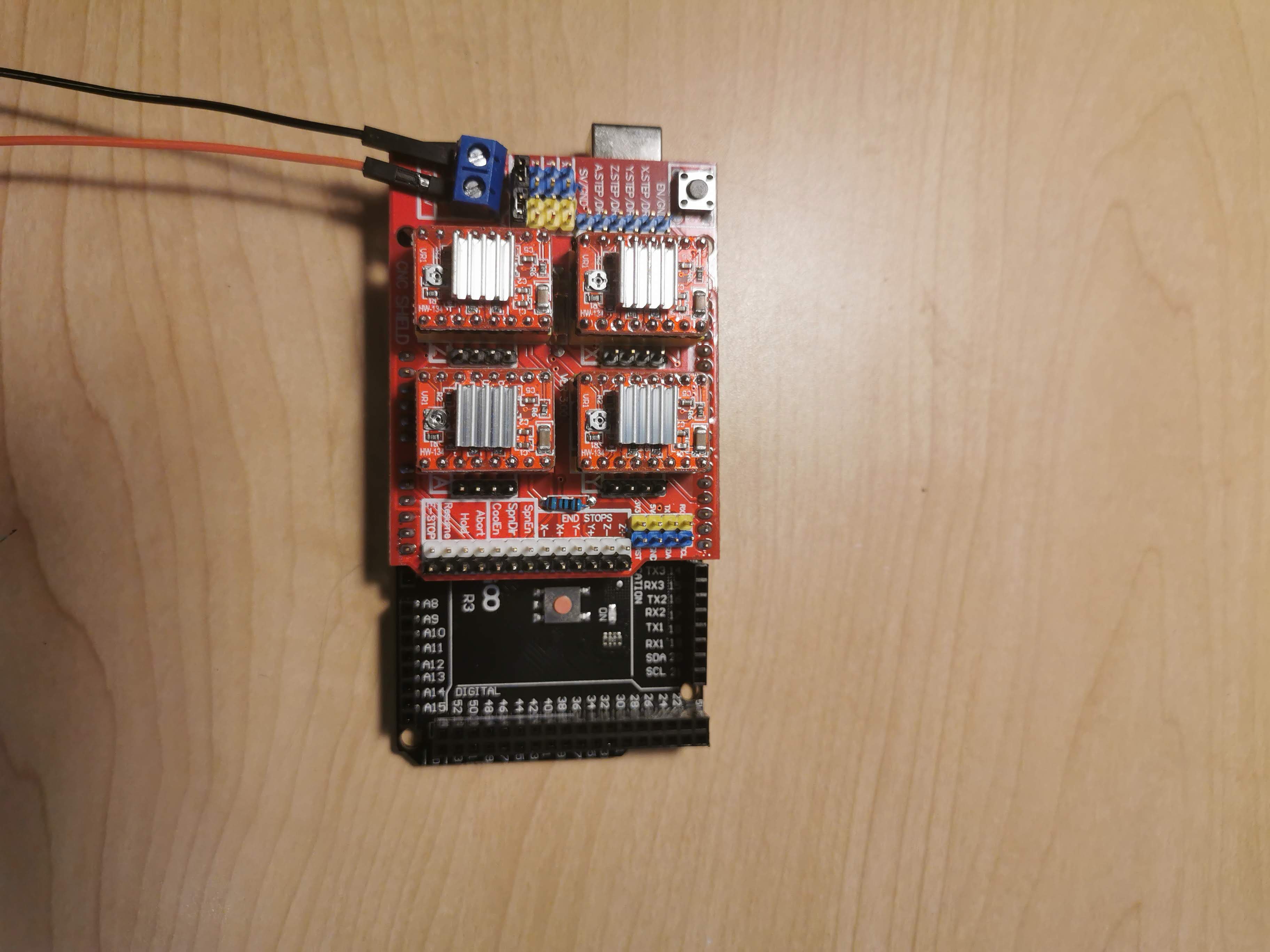
The Electronics
Currently all actuators are open-loop control as this arm does not require a high torque load where steps could be lost, however I have ordered several AS5600 encoders to add closed loop control swell as implement an accurate homing feature.
The steppers are controlled using the A4988 controllers in the 1/4 step configuration. I developed a simple proto-board circuit to the electronics control box (to be built).

 Antonio Regueira
 Aaed Musa
 Petar Crnjak
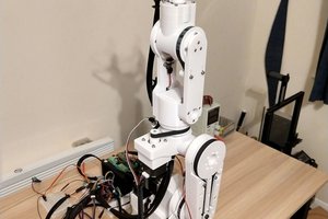
Would you mind to share your solidworks files?i want to export Urdf xml