 Greg Duckworth
So I have done some engineering analysis and some prototyping work and I now have the next version of the rotary joint that I would like to manufacture and test. First; How I got to this point.
Holding Moment Calculations
So I have previously documented a set of calculations that can be done to derive the holding torque for face-to-face contact of two discs. The resulting formula is:
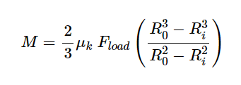
Where M is the holding moment, µ is the coefficient of friction, F is the applied force, Ro is the Outside Diameter and Ri is the Inside Diameter.
This results in some interesting conclusions:
µ vs Ro
The holding moment is directly proportional to the coefficient of friction. This means that achieving the highest coefficient of friction allows the lowest clamping force to hold a given moment. The moment is also proportional to the outer radius of the disc. The subtlety here is that the overall size of the joint is given by the diameter not the radius and so it is very beneficial to increase the coefficient of friction against increasing the radius of the disc.
To illustrate this, for a given force (8 kN), a required holding moment (180 Nm) and a coefficient of friction of 1, the disc must have an Ro of 25 mm and an Ri of 20 mm. If the coefficient of friction is reduced to 0.6 then the disc needs an Ro of 40mm and an Ri of 35mm. This changes a 50 mm diameter disc to an 80 mm diameter disc, greatly increasing the mass and making manufacture more difficult. (The difference between Ro and Ri was maintained at 5 mm in both instances to simplify comparison)
Ri and Ro
The equation for the holding moment of a circular contact is directly proportional to the radius, given that there is no inner diameter. The holding moment for a disc is more complicated and the relationship between the holding moment and Ro and Ri is not immediately intuitive.
For a given force, the holding moment increases as Ro increases. This is intuitive.
For a given force, the holding moment decreases as Ri DECREASES. This was not intuitive to me at first.
For example:
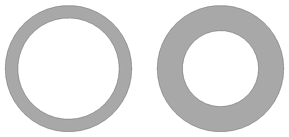
So for MORE surface are you get less force???
Okay, so I can now think of this in terms of a certain pressure as a certain radius. The case with the larger ID (left) has a higher pressure and all of that higher pressure is spread over a larger radius. The case with the smaller ID (right) has a lower pressure and that pressure applies over a smaller radius than the case on the left.
If anyone knows of a better explanation, I would love to hear it. Please message me or comment here, I would love to understand this better.
Anyway, the conclusion of this exercise was a table:
| µ | Ro (mm) | Ri (mm) | Desired M (Nm) | Required Force (kN) |
|---|---|---|---|---|
| 1.0 | 25 | 15 | 180 | 8.8 |
| 1.0 | 25 | 20 | 180 | 8.0 |
| 0.8 | 25 | 20 | 180 | 10 |
| 0.6 | 25 | 20 | 180 | 13.2 |
| 0.4 | 25 | 20 | 180 | 19.9 |
(A.N. If anyone wants a deeper explanation of how I got to these figures, message me and I will post a very nerdy update with equations and everything)
Hand wheel and bolt selection
The required clamping force is applied using a hand wheel or hand lever. There is a limit to the torque that can be applied by humans and I would like this joint to lock and unlock easily. The bolt must also hold without damaging the threads. It would be preferable if the hand wheel or lever would fit within the silhouette of the joint. Another locking method is the cam-lever. This does not necessarily need to fit within the silhouette of the joint as it does not lock via rotation.
Bolt torque is calculated as follows:
Where T is the torque, D is the diameter of the bolt, F is the force applied, and K is the coefficient of friction. The units are typically in metres and Newtons, however, I find that using mm and kN is more intuitive and does not require a correctional factor. K is typically 0.2 for dry steel on steel and may be as low as 0.12 for very well lubricated bolts. I am using K = 0.16 for my calculations.
For an M8 bolt to apply 8 kN of force, the required torque is 10.2 Nm. This is fairly simple to apply with a hex key, but is much more difficult to apply using a 40 mm diameter hand wheel.
Roy Mech has a handy guide to the strength of the average human here: Human Strength. This gives a mean tightening torque for a human female, on a 40 mm diameter knob, as 3.89 Nm. This value is considerably lower than the required 10.2 Nm.
The required tightening torque can be reduced by reducing the diameter of the bolt:
For an M6 bolt to apply 8 kN of force, the required torque is 7.6 Nm. A grade 8.8 M6 bolt can withstand 11.6 kN force without undergoing plastic deformation. Metric Proof Loads.
7.6 Nm is still too high to be comfortable so the diameter of the joint must be increased to reduce the necessary clamping force and therefore the necessary clamping torque. A larger knob may also help the user apply more torque.
New Design Parameters
The resultant design has a few significant changes. The Ro is 50 mm and Ri is 45 mm, giving an overall diameter of 100 mm. The force required to hold a torque of 180 Nm is 3.8 kN. An M6 bolt is used to provide the clamping force, requiring a tightening torque of 3.6 Nm. This is slightly above the stated human torque but I will choose a larger hand wheel to compensate.
To CAD!
Discussions
Become a Hackaday.io Member
Create an account to leave a comment. Already have an account? Log In.