 Leonardo Ward
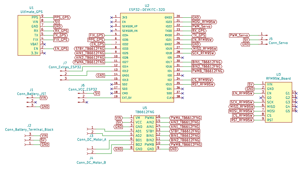
The second electronic design for the buoy (Buoy B) will contain the following main components:
- ESP32 DEVKITC 32D
- Ultimate GPS
- TB6612FNG
- Servo connection
- RFM95W (LoRa)
Once we selected the main components we created a schematic and designed the PCB.
The main characteristic that differentiates the design of Buoy A and Buoy B is that the first one contains the GSM module, and second one doesn't have it.
Schematic
Bill Of Materials
| Quantity | Name | Description |
| 1 | Adafruit Ultimate GPS | GPS Module |
| 1 | RFM95W LoRa Radio | LoRa Module |
| 1 | ESP32-DEVKITC-32D | ESP32 Module |
| 1 | TB6612FNG MOTOR DRIVER BOARD | Motor Driver |
| 1 | TERM BLK 2P SIDE ENT 5.08MM PCB | Terminal Block for the DC Motor |
| 1 | TERM BLK 3P SIDE ENT 5.08MM PCB | Terminal Block for the Vin, 5V and GND |
| 1 | CONN HEADER R/A 3POS 2.5MM | 7.4V 2 cell Battery Connector |
| 2 | CONN HEADER VERT 40POS 2.54MM | Male Headers |
| 1 | CONN JUMPER SHORTING .100" GOLD | Vin selector for the ESP32 |
| 1 | GPS Antenna | GPS Antenna |
| 2 | LoRa and GSM Antenna | LoRa and GSM Antenna |
Since this is the first version of the design, we won't solder the breakout boards (GPS, LoRa, Motor Driver and ESP32) directly to our PCB (Buoy B), instead we will connect them using headers. Female headers will be soldered to the PCB and male headers to the breakout boards. The use of headers will help us to debug the design by connecting and testing one of the modules at the time. The following table presents the required headers:
| Quantity | Name | Description |
| 2 | CONN HDR 19POS 0.1 TIN PCB | Female Header used to connect the ESP32 |
| 2 | CONN HDR 8POS 0.1 TIN PCB | Female Header used to connect the Motor Driver (TB6612FNG) |
| 2 | CONN HDR 9POS 0.1 GOLD PCB | Female Header used to connect the GPS and the Lora Module |
| 1 | CONN HDR 5POS 0.1 GOLD PCB | Female Header used to connect the Lora Module |
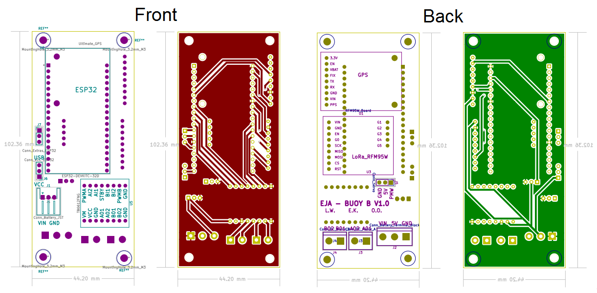
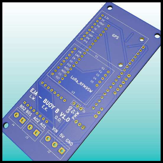
PCB Layout
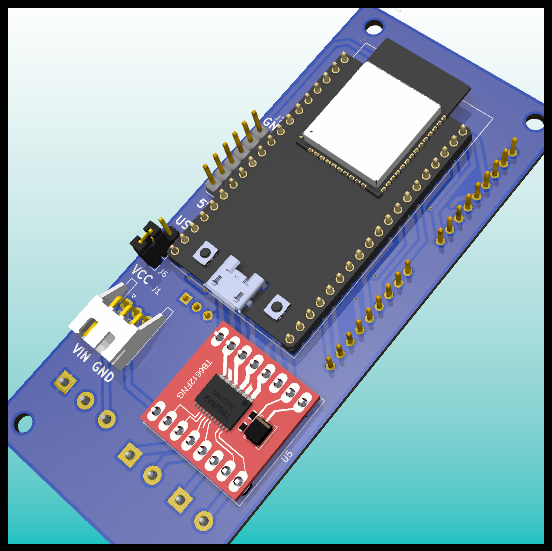
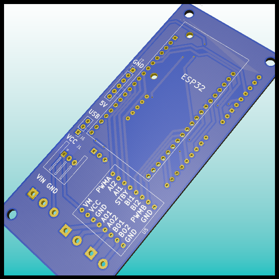
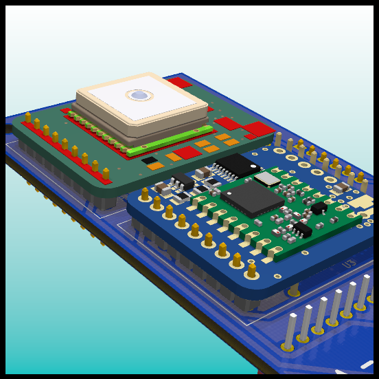
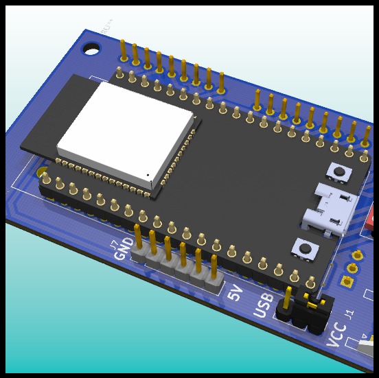
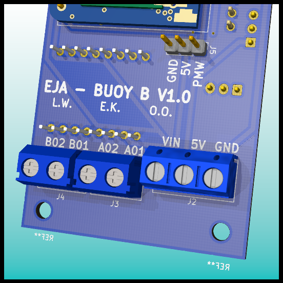
3D Model


Discussions
Become a Hackaday.io Member
Create an account to leave a comment. Already have an account? Log In.