 EK
EKThis update brings photos of the enclosure cuts and HDPE test coupons from the DesignLab, as well as the first version of the top plate of the spool box to be cut.
Here is the enclosure (polycarbonate nalgene water bottle) being cut. The cut location is just below where the curve ends for the start of the main width. Bruce from DesignLab made the cut:

Photo credit: Giovanni at the DesignLab
Read on for more about how it turned out, and see photos of the HDPE test coupons!
The nalgene was supported by a jig that we designed and then was 3D printed at DesignLab:

I wasn’t too sure how the tolerances were going to work, but it looks like it fit onto the exterior of the nalgene just fine. The cut was clean, though sanding proved to be a bit trickier. Here’s the result:
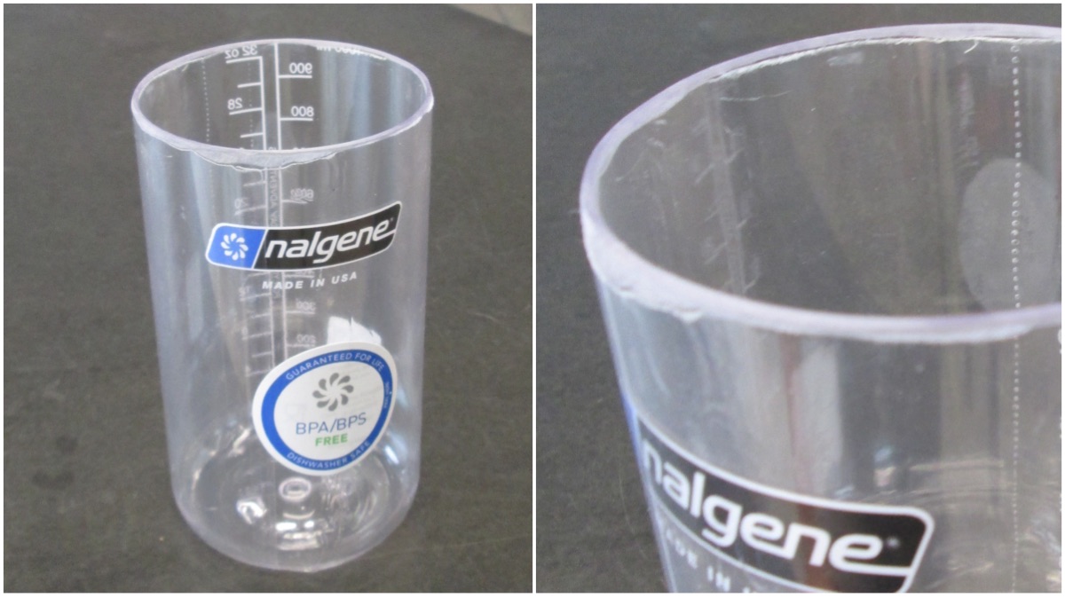
Photo credit: Giovanni at the DesignLab
This will suit our purposes very well! The larger enclosure will be for Buoy A, and we will be able to fit a Raspberry Pi with a camera on it for the fish monitor. There will need to be an o-ring cap designed for this, and tested, before electronics go inside.
There are also the HDPE test cuts, these were milled using a 1/16” bit. The material is 3/8" (0.375”) thick; the bit didn’t reach the entire way. From the photos it looks fine for testing purposes. Check out the t-slot milled pieces.

Photo credit: Giovanni at the DesignLab
There’s extra space in the design of the t-slot, and it looks like the cut radius is fine on the piece without the dogbone. Here’s what the tabs look like:
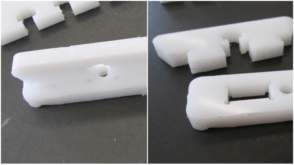
Photo credit: Giovanni at the DesignLab
It fits! Glad that the alignment worked out. In this week’s design review, we were able to receive feedback on the design presented in update #06. Here are some of the changes that have been made:

Here is the new piece:
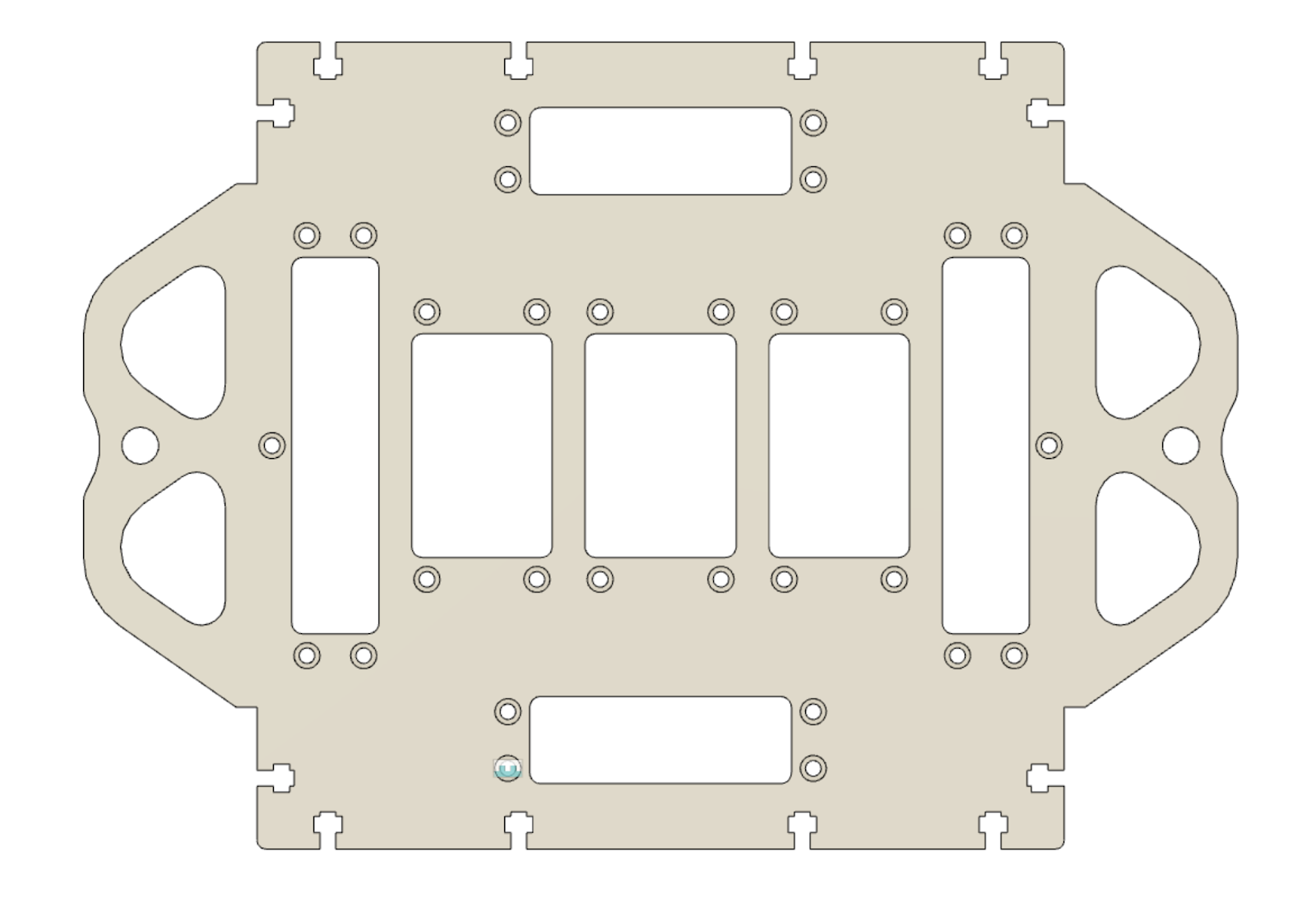
Of particular interest are the areas that stick out of the side. These are where the ropes will attach that go to the gear. The previous revision, the material was thin around this, and had some areas that were not very smooth in terms of curvature. The changes in the updated version reflect this. Additionally, repositioning of some of the fastener areas changed to provide nicer spacing between the countersink area and the cutout.
That’s all for this update. After update #06, the priority was re-evaluated again to work on the design pieces for the buoy. The strategy was then pivoted to allow for extra time designing and testing the pieces properly. More about this in a future update #08.
The top plate design was sent to Giovanni @Giovanni and Bruce today, so it can be milled on Monday or Tuesday. The circuit boards are somewhere in Ontario, however not arrived in this city yet. Shoutout to Bruce @brucejdii for his time and effort fabricating these pieces!
The next steps are (...were) to work on the design for the buoy and 3D print those pieces. Following that, for the spool box the next steps are to complete the design for the other sides, and the spool and sleeve bearing itself.
Discussions
Become a Hackaday.io Member
Create an account to leave a comment. Already have an account? Log In.